
User's Manual

3
ON
ALARM ACCESSORY RCVR
SEQ1
SEQ2
LEARN
BLU
ORG
WHT
GRN
R B G
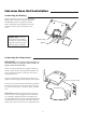
Connect #1 wire from the
RELAY OUTPUT terminals
on the keypad to WHT
terminal on the gate opener
control board.
Connect #2 wire
from the RELAY OUTPUT
terminals on the keypad to the
GRN terminal on the gate
opener control board.
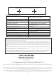
PRO-1000/2000, PRO-SL1000/SL2000 and Old Mighty Mule
Control Boards
#1
#2
RELAY
OUTPUT
AC/DC
POWER IN
123456789
+
0
–
Jumper ON
Jumper OFF
Hard-wire from Gate Opener
Power Supply from
Opener Battery
#
1
#
2
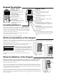
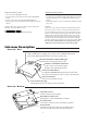
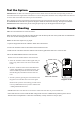
Step 2: For hard-wired communication between the keypad and gate opener, using 16 gauge
(AWG) stranded, direct burial, low voltage wire (part no. RB509) strip the wires back 3/16”
and attach the wires to the terminal block marked RELAY OUTPUT on the keypad control
board as shown to the right. Connect the other end to the opener’s control board as shown in
Control Board Connections section below.
To wire the power supply to the keypad, attach the wires to the AC/
DC POWER IN terminal on the keypad control board as shown
to the right. Connect the other end to the opener’s battery - one
end to the POSITIVE (RED) pole and the other to the NEGA-
TIVE (BLACK) pole.
NOTE: For a hard-wired application
the jumper between the two terminals
on the keypad control board must be
connected (ON) as shown. This will
disable the 318 MHz RF transmitter.
Step 3: Slide the keypad into the cover and secure with the small screws provided.
Step 4: Turn the power to the opener OFF. Remove the opener control board cover and feed enough of the
low voltage wire from the keypad through a strain relief to reach the gate opener control board terminals.
Step 5: Attach the wires from the keypad to the opener control board terminal blocks as shown below.
Step 6: Replace the control board cover and turn the power switch ON. Test the keypad by entering 1 2 3 4.
Step 7: Program your ‘Personal Master Code’ and any additional entry codes (for a total of 25 entry codes).
See Programming the Keypad section.
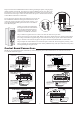
Control Board Connections
1
2
ABC
3
DEF
4
GHI
5
JKL
6
MNO
7
PRS
8
TUV
9
WXY
0
CALL
STATUS
PROGRAM
CALLING
GRANTED
NOTE: If your control board doesn’t look like any of these diagrams, please call Technical Service at 1-800-543-1236 or 850-
575-4144 for additional support.
GRN BLK RED
RECEIVER
COM COM
C
L
OS
E
CYCLE
CLOSE
SAFETY
EXIT
OPEN
SHADOW
LOOP
CLOSE
EDGE
OPEN
EDGE
J
1
1
J11
J8
J12
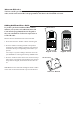
GTO/PRO DC Powered PRO-SW3000
and PRO-SW4000 Control Boards
Connect #1 wire from the
RELAY OUTPUT terminals on
the keypad to CYCLE terminal on
the gate opener control board.
Connect #2 wire from
the RELAY OUTPUT
terminals on the keypad
to the COM terminal on
the gate opener control
board.
#1
#2
RECR
GRN
BLK
RED
EXIT
SAFETY
EDGE
CYCLE
COMMON
LINK
Mighty Mule 350 Control Board
Connect #1 wire from the
RELAY OUTPUT terminals
on the keypad to CYCLE
terminal on the gate opener
control board.
Connect #2 wire from the RELAY
OUTPUT terminals on the keypad
to the COMMMON terminal on
the gate opener control board.
#1
#2
RECEIVER
COM COM
CYCLE
CLOSE
SAFETY
EXIT/
OPEN
SHADOW
LOOP
CLOSE
EDGE
OPEN
EDGE
BLKGRN RED
Mighty Mule 500 & 502
Control Boards
Connect the #1 wire from
RELAY OUTPUT terminals on the
keypad to the CYCLE terminal on
the opener control board.
Connect the #2 wire from
the RELAY OUTPUT
terminals on the keypad to
one of the COMMON
terminals on the opener
control board.
#1
#2
RECEIVER
ALM
GTO RCVR.
COM
GRN
BLK
RED
CYCLE
SAFETY
EXIT
SHADOW
OPEN
EDGE
COM
CONTROL INPUTS
CLOSE
EDGE
Connect #1 wire from
the RELAY OUTPUT terminals
on the keypad to CYCLE terminal
on the gate opener control board.
Connect #2 wire from the
RELAY OUTPUT terminals
on the keypad to the COM
terminal on the gate opener
control board.
#1
#2
GEN-3 (Blue) Control Boards
COM
COM
COM
GTO Inc.
SX4000 L
CYCLE
SAFETY
OPEN EDGE
RUN 2
OPEN
CLOSE
STOP
COM
COM
COM
SHADOW
LOOP
Connect #1 wire from the
RELAY OUTPUT
terminals on the keypad to
CYCLE terminal on the
gate opener control board.
Connect #2 wire from the
RELAY OUTPUT terminals
on the keypad to the COM
terminal on the gate opener
control board.
#1
#2
GTO/PRO GP-SL100 and GP-SW100
Control Boards