
User's Manual

22
Mighty Mule 202
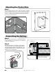
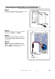
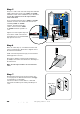
Step 1
Strip approximately
3
/16" of insulation from each wire of
the FIRST opener power cable. Insert the power cable into
a strain relief slot. Bring approximately 4" of wire into the
control box. Insert the stripped power cable wires into the
appropriate terminals on the FIRST OPR. terminal block.
The white wire should be inserted into the WHT terminal, the
green wire into GRN, the red wire into RED, and the black
wire into the BLK, terminals.
Tighten the set screws against the end of the wires. A dab of
petroleum jelly on each terminal will help prevent corrosion.
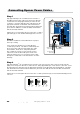
Step 3
Strip approximately
3
/16" of insulation from each wire of the 32 foot power cable. Twist each exposed wire
tightly. Insert the power cable into a strain relief slot. Bring approximately 4" of wire into the control box. Insert
the stripped power cable wires into the appropriate terminals on the SECOND OPR. terminal block. The white
wire should be inserted into the WHT terminal, the green wire into GRN, the red wire into RED, and the black
wire into the BLK, terminals.
Tighten the set screws against the end of the wires. A dab of petroleum jelly on each terminal will help prevent
corrosion.
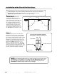
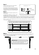
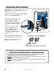
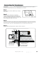
Step 2
Review the Installation Overview illustration on page 11
before proceeding.
Cut a slot into the driveway to accommodate PVC
conduit (not provided). The buried conduit will protect
the 32 foot power cable from automobile tires, lawn
mower blades, weed eaters, and grazing animals.
PVC conduit also allows for easy removal of power
cable in the event the SECOND opener needs to be
replaced. Pull the 32 foot second opener power cable
through the conduit and secure them into the slot in the
driveway.
Connecting Opener Power Cables
FIRST Opener
Power Cable
SECOND Opener
Power Cable
Strain Relief Slots
VAR5
VAR6
K1
PF1
K2
BATT +
BATT –
K3
K4
VAR4
VAR3
VAR2
VAR1
MIN
MAX
OFF
JP1
REMOVE JUMPER FOR
PUSH TO OPEN OPTION
120
SEC.
GTO Inc. Tallahassee, FL
R4722
STALL FORCE
OPEN < JOG > CLOSE
PWR.
SET
LIMIT
1st OPR.
2nd OPR.
STATUS
AUTO CLOSE
SFTY.
EXIT
CYCLE
EDGE
SENSOR
COMMON
LOCK+
LOCK–
WHT
GRN
RED
BLK
WHT
GRN
SECOND OPR.FIRST OPR.
RED
BLK
14 VAC
OR
SOLAR
ON OFF
2^aaTRc
Fa^]V Fa^]V
FXaT
CTa\X]P[
1[^RZ
CTa\X]P[
1[^RZ
CTa\X]P[
1[^RZ
FXaT FXaT