
User's Manual

Mighty Mule 202
21
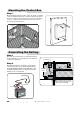
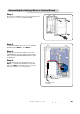
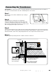
Step 1
Remove the CONTROL BOX cover by removing the four
(4) screws to access the CONTROL BOARD.
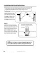
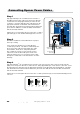
Connecting the Battery Wires to Control Board
VAR5
VAR6
K1
PF1
K2
BATT +
BATT –
K3
K4
VAR4
VAR3
VAR2
VAR1
MIN
MAX
OFF
JP1
REMOVE JUMPER FOR
PUSH TO OPEN OPTION
120
SEC.
GTO Inc. Tallahassee, FL
R4722
STALL FORCE
OPEN < JOG > CLOSE
PWR.
SET
LIMIT
1st OPR.
2nd OPR.
STATUS
AUTO CLOSE
SFTY.
EXIT
CYCLE
EDGE
SENSOR
COMMON
LOCK+
LOCK–
WHT
GRN
RED
BLK
WHT
GRN
SECOND OPR.FIRST OPR.
RED
BLK
14 VAC
OR
SOLAR
ON OFF
VAR5
VAR6
K1
PF1
K2
VAR4
VAR3
VAR2
VAR1
MIN
MAX
OFF
JP1
REMOVE JUMPER FOR
PUSH TO OPEN OPTION
120
SEC.
GTO Inc
FL
R472
STALL FORCE
OPEN < JOG > CLOSE
PWR.
SET
LIMIT
1st OPR.
2nd OPR.
STATUS
AUTO CLOSE
SFTY.
EXIT
CYCLE
EDGE
SENSOR
COMMON
LOCK+
LOCK–
WHT
GRN
RED
BLK
WHT
GRN
SECOND OPR.
FIRST OPR.
RED
BLK
14 VAC
OR
SOLAR
ON OFF
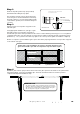
Strain Relief Slots
Battery Harness Cable
from Battery
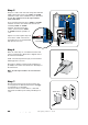
Step 2
Locate the BATTERY wires from on the CONTROL
BOARD marked "BATT +" and "BATT –".
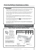
Step 3
Run the Harness wires through the control box
STRAIN RELIEF SLOT as shown, leaving enough
wire to reach the BATTERY WIRE PLUGS from the
control board.
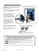
Step 4
Plug the BLACK wire into the BLACK wire fron
"BATT ––" terminal and the RED wire to the RED
wire from "BATT +" terminal. Reverse connection
will cause damage to the control board.