
User's Manual
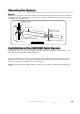

Mighty Mule 202
19
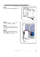
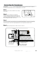
Closed Position
Positive Stop Plates
OPTIONAL Closed Position
Ground Stop Post
Post Bracket Assembly
Gate Bracket
At this stage of the installation, the openers should be installed on the
gate leaves and the open and closed position stops should be in place.
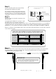
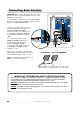
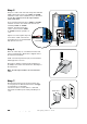
Step 3
Attach a vertical closed position stop plate to the
SECOND gate.
Using appropriate hardware for your type of gate
attach the vertical closed position stop plate to
the SECOND gate frame at the point where it will come in contact with the ground stop post.. Do not tighten it
completely at this time. You must slide the closed position stop plate toward the ground stop until they touch
(Illustration C). Once you have moved the stop plate to the correct position, tighten its hardware completely.
NOTE: For a push-to-open installation (gate opens out from the property) attach the closed position stop plate
to the outside of the gate.
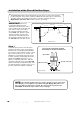
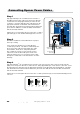
Step 2
Install a low profile ground stop (not provided)
beneath the SECOND gate stop plate.
The ground stop needs to be positioned near the
end of the gate as shown in Illustration A and may
be made of metal or concrete and should be firmly
secured in the ground (we recommend setting it in
concrete).
1Z]aSR>]aWbW]\Ab]^>ZObS[]c\bSR
]\bVSA31=<25/B3
1Z]aSR>]aWbW]\Ab]^>ZObS
:]e>`]TWZS Ground Stop
W\<SO`bVS1S\bS`]T2`WdSeO
g
FRONT VIEW
SIDE VIEW
;]c\bDS`bWQOZZg
Illustration C
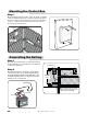
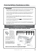
CHECK LIST
t5IFHBUFTBSFQMVNCMFWFMBOETXJOHTTNPPUIMZPOJUTIJOHFT
t"QMBUFPSTVQQPSUXBTBEEFEGPSUIFHBUFCSBDLFUJGOFDFTTBSZ
t5IFPQFOFSJTMFWFMBOENPVOUFEPOUIFDFOUFSMJOFPGUIFHBUF
t5IFDMPTFEQPTJUJPOTUPQQMBUFJTJOTUBMMFEJOQMBDF
Step 4
Return the gates to their open positions and reconnect the gate openers front mounts to the gate brackets
using the bushings, clevis pins and hairpin clips. Check the checklist below to be sure that you have
completed the important installation steps.