
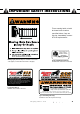
User's Manual

14
Mighty Mule 202
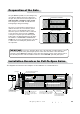
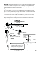
Determining the Mounting Position
of the Post Bracket Assembly and the Gate Bracket
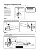
Step 3
8JUIUIFHBUFJOUIFPQFOQPTJUJPOVQUPGSPNJUTDMPTFEQPTJUJPOBOEUIFPQFOFSGVMMZSFUSBDUFE
adjust the post bracket assembly and gate bracket until the opener is level. While holding the opener level,
use C-clamps to temporarily keep the post bracket assembly and gate bracket in their respective positions
on the fence post and gate.
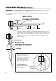
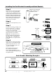
Step 1
Insert the
3
/8" x 1
1
/2"
bolt through the center
hole of the post brackets
and post pivot bracket
as shown. Fasten a
3
/8"
washer and
3
/8" lock nut
on the end of the bolt.
DO NOT overtighten the
lock nut because the
post pivot bracket will
have to be adjusted later.
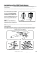
Step 2
Attach post bracket assembly to the rear mount of the opener with a clevis pin and a 3/8" washer. Secure
the clevis pin with a hairpin clip. Attach gate bracket to the front mount of the opener with a clevis pin and a
3/8" bushing. Secure the clevis pin with a hairpin clip
3/8" x 1-1/2" Bolt
3/8" Lock Nut
Post Pivot Bracket
Post Bracket
Post Bracket Assembly
3/8" Washer
REMINDER:
The following steps are
intended for pull-to-open
gate installations only.
Clevis Pin
Hairpin Clip
Post Bracket Assembly
3/8” Washer
Rear Mount
Opener
Clevis
Pin
Hairpin Clip
Gate Bracket
Front Mount
Bushing
Fence Post
Gate In Open Position
LEVEL horizontal cross member
Post Bracket Assembly
Gate Bracket
Level Opener