Installation Manual for the WARNING! This equipment is similar to other gate or door equipment and meets or exceeds Underwriters Laboratory Standard 325 (UL 325). However, gate equipment has hazards associated with its use and therefore by installing this product the installer and user accept full responsibility for following and noting the installation and safety instructions. Failure to follow installation and safety instructions can result in hazards developing due to improper assembly.
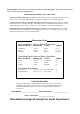
The Mighty Mule® Gate Opener is intended for use with vehicular swing gates. The opener can be used in Class I, Class II and Class III applications. VEHICULAR GATE OPENER CLASS CATEGORIES Residential Vehicular Gate Opener-Class I: A vehicular gate opener (or system) intended for use in a home of one-to-four single family dwelling, or a garage or parking area associated therewith.
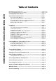
Table of Contents KEEP THESE INSTRUCTIONS FOR FUTURE REFERENCE Gate Opener Class Categories ------------------------------------------------------------ inside cover Units and Standards Conversion Chart ------------------------------------------------ inside cover PLEASE READ THIS FIRST! ------------------------------------------------- page iii Important Safety Instructions ---------------------------------------------- page 1 Disconnecting the Opener ----------------------------------------------------
® E-Z GATE OPENERS PLEASE READ THIS FIRST! Thank you for purchasing a Mighty Mule® 202 E-Z Gate Opener(50hT EP JU ZPVSTFMG BVUPNBUJD HBUF opener! When correctly installed and properly used, your Mighty Mule® E-Z Gate Opener will give you many years of reliable service. Please read the following information and watch the enclosed video to ensure you have the correct system for your particular needs.
IMPORTANT SAFETY INSTRUCTIONS Because automatic gate openers produce high levels of force, consumers need to know the potential hazards associated with improperly designed, installed, and maintained automated gate opener systems. Keep in mind that the gate opener is just one component of the total gate operating system. Each component must work in unison to provide the consumer with convenience, security, and safety. This manual contains various safety precautions and warnings for the consumer.
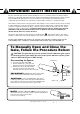
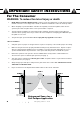
IMPORTANT SAFETY INSTRUCTIONS For The Consumer WARNING: To reduce the risk of injury or death: 1. READ AND FOLLOW ALL INSTRUCTIONS. Failure to meet the requirements set forth in the instruction manual could cause severe injury and/or death, for which the manufacturer cannot be held responsible. 2. When designing a system that will be entered from a highway or main thoroughfare, make sure the system is placed far enough from the road to prevent traffic congestion. 3.
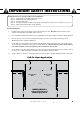
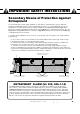
IMPORTANT SAFETY INSTRUCTIONS Entrapment Zones for a proper Pull-To-Open installation: Zone 1 – leading edge of the gate and the fence post. Zone 2 – between the gate and the gate post. Zone 3 – the path of the gate. Zone 4 – the space between the gate in the open position and any object such as a wall, fence, tree, etc. Zone 5 – pinch points between the opener and gate. II. During Installation 1. Install the gate opener on the inside of the property and fence line.
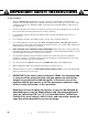
IMPORTANT SAFETY INSTRUCTIONS III. After Installation 1. Attach the warning signs (included) to each side of the gate to alert the public of automatic gate operation. It is your responsibility to post warning signs on both sides of your gate. If any of these signs or warning decals become damaged, illegible or missing, replace them immediately. Contact GTO for free replacements. 2. The gate is automatic and could move at any time, posing a serious risk of entrapment.
IMPORTANT SAFETY INSTRUCTIONS Secondary Means of Protection Against Entrapment As specified by Gate Opener Safety Standard, UL 325 (30A.1.1), automatic gate openers shall have an inherent entrapment sensing system, and shall have provisions for, or be supplied with, at least one independent secondary means to protect against entrapment. The Mighty Mule® utilizes Type A, an inherent (i.e., built-in) entrapment sensing system as the primary type of entrapment protection.
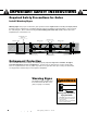
IMPORTANT SAFETY INSTRUCTIONS Required Safety Precautions for Gates Install Warning Signs Warning signs alert people of automatic gate operation and are required when installing the Mighty Mule® E-Z Gate Opener. Furthermore, a walk-through gate must be installed if pedestrian traffic is expected near the vehicular gate. We recommend using the GTO Bulldog Pedestrian Gate Lock (Call the GTO Sales Department) for controlled access.
IMPORTANT SAFETY INSTRUCTIONS ! These warning labels should be found at the locations specified below. If any are missing, immediately contact GTO for replacements. GTO DC SW200 Series Conforms to UL325 5th Edition Standards Serial No. mm/dd/yy MM202-0000000 GTO, Inc.
Parts List - Opener and Mounting Hardware ! WARNING Installation DVD (1) Moving Gate Can Cause Injury Or Death Battery Wire Harness (1) Transformer (1) RB502 1. KEEP CLEAR! Gate may move at any time. 2. Do not allow children to operate gate or play in gate area. 3. This gate is for vehicles only. Pedestrians must use a separate entrance.
Tools Needed t 1PXFS %SJMM t 0QFO &OE 8SFODIFT 1/2", and 9/16" t "EKVTUBCMF 8SFODI t 3/8" Drill Bit t )BDLTBX PS )FBWZ %VUZ #PMU $VUUFST t 4NBMM 'MBU #MBEFE 4DSFXESJWFS t 1IJMMJQT 4DSFXESJWFS -BSHF t 5BQF .
Technical Specifications MIGHTY MULE® 202 E-Z GATE OPENER DRIVE t -PX GSJDUJPO TDSFX ESJWF MJOFBS BDUVBUPS SBUFE GPS ' UP ' $ UP $ t 1PXFSFE CZ B 7 NPUPS XJUI JOUFHSBM DBTF IBSEFOFE TUFFM HFBS SFEVDFS .PUPS TQFFE SFEVDFE UP SQN Generates 520 inch lb. of torque at 12 V. t .
Preparation of the Gate The gate must be plumb, level, and swing freely on its hinges. Wheels must not be attached to the gate. The gate must move throughout its arc without binding or dragging on the ground. Note that gates over 250 lb.. should have ball bearing hinges with grease fittings. Horizontal Cross Member The fence post should be no larger than 6" in diameter and must be secured in the ground XJUI DPODSFUF TP JU XJMM NJOJNJ[F UXJTU PS nFY when the opener is activated.
Installation Overview (continued) IMPORTANT: To achieve optimum leverage for the gate opener and ensure long trouble free service, the gate opener needs to be installed within the following perameters. The diagram below shows the optium position for gate opener arm in relation to the gate in the open and close positions.
Installation of the FIRST Gate Opener IMPORTANT: The gate on the side where the control box is to be mounted will be the FIRST gate opener to install. The position of the post bracket determines the leverage and efficiency of the opener. The post bracket position also sets the clearance between the opener and gate in the open and closed positions. The post bracket works well for installations on round and square fence posts.
Determining the Mounting Position of the Post Bracket Assembly and the Gate Bracket Post Bracket Assembly Step 1 Insert the 3/8" x 11/2" bolt through the center hole of the post brackets and post pivot bracket as shown. Fasten a 3/8" washer and 3/8" lock nut on the end of the bolt. DO NOT overtighten the lock nut because the post pivot bracket will have to be adjusted later. REMINDER: 3/8" x 1-1/2" Bolt The following steps are intended for pull-to-open gate installations only.
IMPORTANT: While determining the mounting point for the post pivot bracket assembly, be sure that the position allows for minimum 1 inch of clearance between the gate and the opener in both the open and closed positions, as well as maintaining the maximum 13" distance explained in the gate installation overview earlier. This position will give the opener the most efficient leverage point for opening and closing the gate and more importantly provides the least possible pinch area.
Installing the Post Bracket Assembly and Gate Bracket Step 5 Mark fence post through middle of bracket slots and drill 3/8" holes Mark reference points for bolt holes on the fence post through middle of bracket slots. Marking reference points in this manner allows room for adjustment when mounting the post bracket assembly and gate bracket. After marking your reference points, remove the opener and brackets from the fence and gate.
Mounting the Opener Step 9 Attach the opener to the securely bolted post bracket assembly and gate bracket using clevis pins, bushings, and hairpin clips, or optional Pin Locks (see Accessory Catalog). Verify that the opener is level and adjust the post bracket assembly if necessary.
Installation of the Closed Position Stops The Mighty Mule® Gate Opener firmly holds the gate in the closed position using the positive stop plate. The positive stop helps stabilize the gate leaf in the closed position. To further enhance the stability and security of your gate, install the optional Mighty Mule® Automatic Gate Lock (see Accessory Catalog). IMPORTANT: You need to determine which side of the driveway you will mount the control box.
Step 2 1Z]aSR >]aWbW]\ Ab]^ >ZObS []c\bSR ]\ bVS A31=<2 5/B3 The ground stop needs to be positioned near the end of the gate as shown in Illustration A and may be made of metal or concrete and should be firmly secured in the ground (we recommend setting it in concrete). ;]c\b DS`bWQOZZg Install a low profile ground stop (not provided) beneath the SECOND gate stop plate. SIDE VIEW 1Z]aSR >]aWbW]\ Ab]^ >ZObS :]e >`]TWZS Ground Stop W\
Mounting the Control Box Step 1 Mount the Battery Box using the screws (provided) or another secure mounting method. The control box must be mounted at least 3 feet above the ground to protect it from rain splash, snow, etc., and at least 3 feet from an AC power source to prevent electrical interference.
Connecting the Battery Wires to Control Board Step 1 Remove the CONTROL BOX cover by removing the four (4) screws to access the CONTROL BOARD. Step 2 Locate the BATTERY wires from on the CONTROL BOARD marked "BATT +" and "BATT –". STATUS 1st OPR. OPEN < JOG > CLOSE Step 3 Run the Harness wires through the control box STRAIN RELIEF SLOT as shown, leaving enough wire to reach the BATTERY WIRE PLUGS from the control board. 2nd OPR. MIN MAX OFF STALL FORCE PWR. 120 SEC.
Connecting Opener Power Cables Step 1 Strip approximately 3/16" of insulation from each wire of the FIRST opener power cable. Insert the power cable into a strain relief slot. Bring approximately 4" of wire into the control box. Insert the stripped power cable wires into the appropriate terminals on the FIRST OPR. terminal block. The white wire should be inserted into the WHT terminal, the green wire into GRN, the red wire into RED, and the black wire into the BLK, terminals. STATUS 1st OPR.
Powering Options: Transformer or Solar IMPORTANT t 5IF .JHIUZ .VMF JT EFTJHOFE BOE JOUFOEFE GPS VTF XJUI B 7PMU BVUPNPUJWF PS NBSJOF UZQF battery. The battery must be placed inside a weatherproof case and located within 6 feet of the control box. The 8 foot harness supplied connects the battery to the control board. t 5IF CBUUFSZ DIBSHF JT NBJOUBJOFE CZ UIF 7PMU USBOTGPSNFS JODMVEFE or by using optional solar panel(s).
Connecting Solar Panel(s) IMPORTANT: Never connect the transformer and a solar panel to the opener control board at the same time. It will damage the control board. STATUS 1st OPR. If you are using the transformer included with the Mighty Mule 202 to charge the opener battery, skip this section and go to "CONNECTING BATTERY". OPEN < JOG > CLOSE 2nd OPR. MIN MAX OFF STALL FORCE PWR. 120 SEC. AUTO CLOSE SET LIMIT REMOVE JUMPER FOR PUSH TO OPEN OPTION SFTY.
Connecting the Transformer IMPORTANT: Use either transformer or solar panel. DO NOT connect both transformer and solar panels to the opener control board at the same time. It will damage the control board. Step 1 Make sure the power switch is OFF before proceeding to the next step. Step 2 Select the electrical outlet where you will plug the transformer. Measure the distance from this outlet to the control box following the path where the wire will be laid.
Step 5 Strip 3/16" off the ends of the low voltage wire and twist tightly. Attach these ends to the '14VAC or SOLAR' terminals located on the terminal block (see illustration at right). Be certain not to let the exposed wires touch each other! MAX OFF STALL FORCE 120 SEC. AUTO CLOSE REMOVE JUMPER FOR PUSH TO OPEN OPTION SFTY. VAR1 EXIT JP1 VAR2 CYCLE VAR3 EDGE SENSOR VAR4 COMMON VAR5 LOCK+ B PF1 LOCK– K1 WHT K3 GRN GRN K2 RED BLK BATT + K4 SECOND OPR.
Setting the Closed Position Limit for PULL-TO-OPEN installation Must have a transmitter that operates the gate. If not see 'Setting Your Personal Transmitter Code' on page 29. Your Mighty Mule 202 has two Limits 1. OPEN Limit setting: (Gate in the OPEN POSITION / FACTORY SET & NOT ADJUSTABLE) The open limit is when the opener is fully retracted and the gate is in the full open position. 2. CLOSED Limit setting: The CLOSED Limit setting (gate in the CLOSED POSITION).
Stall Force Potentiometer Setting IMPORTANT: For safety reasons the obstruction struction setting or Stall Force on the Mighty Mule® control board comes from the factory set at MIN (minimum). mum). In many gate installations this setting will need to be adjusted to overcome the weight and size of the gates. STATUS OPR. G > CLOSE OPR. MIN 120 SEC. MAX OFF STALL FORCE AUTO CLOSE SET LIMIT The Stall Force potentiometer on the control board operates like a volume control on a radio.
Setting Your Personal Transmitter Code All GTO transmitters are set to a standard code at the factory and are ready to operate your Mighty Mule® Gate Opener®. For your safety and security, however, we strongly recommend that you replace the factory setting with your own personal code. Follow the directions below: 1.
Push to Open Installation Determining The Mounting Position of The Post Bracket Assembly Swinging gates MUST NEVER open into public access areas! "Push-to-Open" gates open out from the property. Push-to-Open Brackets are required for this type of installation (see Accessory Catalog). If you have pull-to-open gates (gate opens into the property), return to page 13; ! & f 0]Zb >caV B] =^S\ 0`OQYSb ]^bW]\OZ OQQSaa]`g In a PUSH-TO-OPEN installation the opener is installed while the gate is in the closed
Step 3 With the gate in the fully closed position and the opener retracted, swing the opener to the gate. Mark reference points for bolt holes on gate cross member through middle of gate bracket slots. The opener must be level. (Some vertical adjustment is possible by sliding the post bracket assembly up and down.) Drill 3/8" holes into the gate cross member as marked. Fasten gate bracket to cross member using (2) 3/8" x 3" bolts, washers, lock washers, and nuts.
Setting the Open Position Limit for PUSH-TO-OPEN installation Note: Must have a transmitter that operates the gate. If not see 'Setting Your Personal Transmitter Code' on page 29. In the PUSH-TO-OPEN application your Mighty Mule 202 has two Limits... 1. CLOSED Limit setting: (Gate in the CLOSED POSITION / FACTORY SET & NOT ADJUSTABLE) The closed limit is the opener fully retracted and thegate in the closed position. 2. OPEN Limit setting: The OPEN Limit setting (gate in the OPEN POSITION).
Connecting Additional Safety Devices Although GTO strongly recommends the use of additional safety devices, we do not endorse any specific brand names. Only use products that are certified and listed to be in compliance with any applicable UL standards (Underwriters Laboratories) and national and regional safety codes. Call GTO Sales at 1-800-543-4283 for information on compatible products for your specific application.
CHARGE POWER INPUTS Control Board Connections NOTE: t "MM BDDFTTPSZ JOQVUT BSF ESZ DPOUBDU OPSNBMMZ PQFO JOQVUT %0 /05 BQQMZ FYUFSOBM WPMUBHF TPVSDFT to these inputs. t "MM BDDFTTPSZ JOQVUT BSF DPOOFDUFE XJUI SFTQFDU UP COMMON terminal.
FIRST OPR. RED GRN WHT BLK 8 RED 7 GRN 6 WHT 5 LOCK– 4 LOCK+ COMMON 3 EDGE SENSOR EXIT 2 CYCLE SFTY.
Visual and Audible Diagnostic Indicators If your gate opener does not function properly after it is installed, use this guide or use the online troubleshooter at http://support.gtoinc.com/support/troubleshooter.aspx before calling the GTO Service Department. t On all gates weighing 250 lb. or more, routinely grease the ball bearing hinges at least 4 times a year; more frequently if the gates are in a coastal area.
The Gate CLOSES Then Opens Again on its Own: 1. 2. 3. 4. Check the position of the mounting brackets and readjust if necessary. Check the gate for binding or hinge damage. Adjust stall force if necessary. Reprogram closed position limits. The Gate OPENS Then Closes Again on its Own: 1. Check the position of the mounting brackets and readjust if necessary. 2. Check the gate for binding or hinge damage. 3. Adjust stall force if necessary. VOLTAGE RATINGS 14 Vac Transformer _________________________ 10.
Warranty Service If your Mighty Mule® Gate Opener is not operating properly, please follow the steps below: 1. First use the procedures found in the Visual and Audible Diagnostic Indicators section (see page 34). 2. Use the Online Troubleshooter at http://support.gtoinc.com/support/troubleshooter.aspx. 3. If you are unable to solve the problem, call the GTO Service Department at (800) 543-1236, or (850) 575-4144.
® E-Z GATE OPENERS ACCESSORIES Accessories are Available From Your Retail Store Solar Panel (FM123) 10 watt This solar powered battery charger is for use with the FM202 gate operator system. Particularly suited for remote installations, each Solar Panel comes with tubular steel support, mounting clips, wire connectors, and 8 ft. of low voltage wire (see Low Voltage Wire for additional wire). The Mighty Mule® control board has clearly labeled terminal connections for easy installation of the Solar Panel.
Accessories are Available From Your Retail Store (con't) Wireless Entry Intercom / Keypad (FM136) Allows owner to screen guest at the gate before allowing access to the property. Keypad also allows owner to give up to 25 programmable entry codes to family, friends or approved delivery personnel. Codes can be permanent or temporary. Can be wireless up to 500 feet. Additional base stations available (F3101MBC).