CR 1212 1 Chapter 1 What is the CR 1212 and How Does It Work? Section A: What is the CR 1212? Section B: How the CR 1212 Works Section C: Commands: Controlling the Tablet’s Operation Section D: Alternative Configurations 3 3 4 6 6 Chapter 2 Assembly and Installation 7 Chapter 3 Interfacing with the Host Section A: Hardware Interfaces Section B: Baud Rate Section C: Communication Protocols Section D: Report Formats 10 10 11 11 12 Chapter 4 Operating Characteristics and Functions Section A: Control
CR 1212 2 Tablet Beep Transmission Control Section D: Reserved Commands 30 31 31 Chapter 5 Guidelines for Writing a Device Driver 32 Chapter 6 Using the CR 1212 37 Chapter 7 Checking the Graphics Tablet Section A: Tablet Calibration Section B: Power (and Proximity) Light Section C: A Quick Functional Check Section D: Diagnostic Functions Echo Self-Test 39 39 39 39 41 41 41 Chapter 8 Operating Environment, Care and Service Section A: Operating Environment Section B: Service Section C: Care and C
CR 1212 3 Chapter 1: What is the CR 1212 and How Does It Work? Section A: What is the CR 1212? CR 1212 is a graphics tablet that acts as an input device. It allows for the translation of graphic information into digital, suitable for a digital device such as a computer.
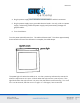
CR 1212 4 Section B: How the CR 1212 Works CR 1212 translates the stylus/cursor position on the tablet into digital information and communicates it to the host. The stylus/cursor position is expressed as an X, Y coordinate pair. One coordinate pair is a report. Valid reports can only be collected when the stylus/cursor is in the tablet’s active area and in proximity: Active area is a 12-inch square area inside the groove on the tablet surface.
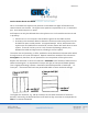
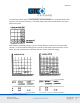
CR 1212 5 As previously stated, reports are measured in counts of resolution. As shown below, each square is one count of resolution. The tablet reports the same coordinates for any point within the square. With different resolution settings, you can receive different reports for the same tablet location. In the illustration below, points A and B are the same physical locations on the tablet, but their coordinates are different because of the resolution setting.
CR 1212 6 Reports are in absolute or relative coordinates. Absolute coordinates are coordinates measured from the tablet’s origin (0, 0). Relative coordinates are measured relative to the last report location. In the illustration above, point B is issued after point A. Therefore, in relative coordinates, point B is measured relative to point A. The tablet defaults to absolute coordinates. However, you can change to relative coordinates with the Relative Coordinates command, described in Chapter 4.
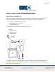
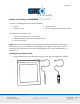
CR 1212 7 Chapter 2: Assembly and Installation The CR 1212 package should include the following: Tablet Stylus or cursor Interface cable CR 1212 Graphics Tablet User’s Guide To assemble and install CR 1212: 1. Connect the stylus/cursor to the tablet. 2. Attach the tablet to the host and power source. 3. Turn on the tablet. NOTE: Always have the computer and tablet power off when attaching or detaching any part of the CR 1212.
CR 1212 8 The cursor and stylus are interchangeable. However, before changing from one to the other, turn off the tablet. (This allows the tablet’s internal software to re-initialize for each device.) 2. Plug the 8-pin phone connector on the interface cable into the tablet. 3. Connect the 25-pin D connector of the interface cable into the host communications port.
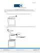
CR 1212 9 4. Plug the power supply barrel connector into the interface cable’s D connector. 5. Plug the power supply into a grounded electrical outlet. Use only a CR 1212 power supply. Substituting a different power supply could permanently damage the graphics tablet. 6. Turn the tablet on. Turn the power (ON/OFF) switch on. The tablet calibrates itself. This takes approximately three seconds and once the calibration is complete, the tablet beeps. The power light is lit when the tablet is on.
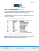
CR 1212 10 Chapter 3: Interfacing with the Host For successful communication between the CR 1212 and its host, they must have the same hardware interface, baud rate, communications protocol and report format. Section A: Hardware Interface The hardware interface for the CR 1212 is an RS-232C with a 25-pin D connector. The pin assignments are listed below.
CR 1212 11 RS-232C Signal Levels NOTE: The source is the EIA Standard RS-232C: Interface between Data Terminal Equipment and Data Communication Equipment Employing Serial Binary Data Interchange, by the Engineering Department of the Electronics Industries Association (Washington, D.C.: EIA, 1969). Section B: Baud Rate The CR 1212 is available with 9600 baud or Autobaud. The standard setting is 9600 baud, unless Autobaud is specifically ordered.
CR 1212 12 Section D: Report Formats The CR 1212 has one of the following report formats: Bit Pad One-compatible format (default) Bit Pad Two-compatible format CR format (similar to MM packed binary format) Bit Pad One- or Two-compatible format for Relative Coordinates (Delta Mode) CR format for Relative Coordinates (similar to MM packed binary format for Delta Mode) The report formats are in (packed) binary. The reports are in counts of resolution, not in inches or millimeters.
CR 1212 13 Bit Pad Two-Compatible Report Format CR Report Format
CR 1212 14 Bit Pad One- or Two-compatible format for Relative Coordinates CR Format for Relative Coordinates Key: LSB is the least significant bit. MSB is the most significant bit. Fa, Fb, Fc and Fd are the flag bits.
CR 1212 15 *Output for Bit Pad One or Two configurations using absolute coordinates. **Output for Bit Pad One or Two configurations using relative coordinates. Sx and Sy are the X and Y coordinate signs. 1 is positive and 0 is negative. PR is the proximity bit. 0 is in-prox and 1 is out-of-prox. PH is the phasing bit, which is always 1. X0, X1, etc. and Y0, Y1, etc. are the X and Y coordinate bits.
CR 1212 16 Chapter 4: Operating Characteristics and Functions The CR 1212 includes a variety of operating characteristics and functions that can be controlled with commands from the host. For example, define: Report flow Tablet resolution Tablet origin location The tablet accepts commands from the host at any rate, except in a few situations. So that the CR 1212 is operable upon arrival at your facility, it is set to predefined default settings.
CR 1212 17 A report issued when the stylus/cursor is out-of-prox is always the last in-prox scanned report. Because the last scanned report may or may not be the last issued report, their values could be different. You may find this occurring when collecting reports at very slow rates. Point Mode In Point Mode, the graphics tablet issues one report when pressing a stylus/cursor button and another when releasing it. (The tip of the stylus is its “button”.
CR 1212 18 Stream Mode In Stream Mode, the graphics tablet issues reports continuously, whether a stylus/cursor button is pressed or not. The Report Rate, described below, controls the number of reports issued per second. When moving the stylus/cursor out-of-prox, the tablet issues the last in-prox scanned report three or four times before it stops transmitting. Switch Stream Mode In Switch Stream Mode, the graphics tablet issues report continuously while pressing a stylus/cursor button.
CR 1212 19 Report Rate The Report Rate function is an adjunct to Stream and Switch Stream modes. Use Report Rate to define the number of reports the tablet issues each second. Each time the tablet is turned on or issues a Reset command, the report rate defaults to 110 or 72 rps, depending on the hardware configuration. By their very nature, low baud rates limit the report rate.
CR 1212 20 NOTE: When using Increment Mode, it’s recommended to use a resolution setting of 50 lpi or higher. How Increment Mode Works The last report issued becomes the center of an imaginary square. The square’s sides measure twice the increment value. The stylus/cursor can move anywhere inside the imaginary square without the tablet issuing a report. When the stylus/cursor touches the square, the increment is met and the tablet transmits a report. This point becomes the center of a new imaginary square.
CR 1212 21 The points issued are: How to Use Increment Mode Send the mode command and then the increment value. The increment value is in counts (of resolution) and can be a decimal whole number from 0 to 90. (The default is zero.) Add 32 (decimal), a required offset, to the desired increment and then convert the sum into your preferred number base.
CR 1212 22 Combining Increment Mode with Other Modes Point Mode and Increment Mode: The stylus/cursor location, at the time Increment Mode is enabled, becomes the center of the initial imaginary square. The tablet issues one report when pressing a stylus/cursor button and another when releasing the button. However, reports are updated only when the increment is met. Remote Request Mode and Increment Mode: When the tablet receives a (Remote Request) trigger from the host, it issues a report.
CR 1212 23 Bit Pad One and Two Configurations: The tablet can have a resolution of up to 508 lpi (6096 counts over a 12-inch axis). Bit Pad configurations are restricted to a maximum of 4095 counts. This, in effect, restricts the resolution to 341 lpi (13 lpmm) over a 12-inch axis. (4095 lpi + 12 inches = 341 lpi) Higher resolutions can be used; however, the active area shrinks accordingly. For example: The axis is measured from the active area origin (0, 0).
CR 1212 24 Use these commands to set the tablet to one of the predefined resolutions listed about. (Resolution is restricted in Bit Pad One and Two configurations. Refer to Section B: Setting the Resolution. Resolution, Definable (Set X, Y Scale) Command Sequence: The purpose of the Definable Resolution function is to let you match the tablet resolution to the resolution of another two-dimensional device, e.g. a computer screen.
CR 1212 25 37 lpi x 12 inches = 444 … is the desired axis resolution The other device may have a resolution expressed as the overall axis values, such as 800 by 1024 pixels. In this case, ensure the length of the corresponding tablet axis divides evenly into the other device’s resolution. If it does not, the tablet truncates the resolution value to a whole number.
CR 1212 26 67 x 12 inches = 804 … is the desired X axis resolution 86 x 12 inches = 1032 … is the desired Y axis resolution 2. Convert the desired axis resolution to a hexadecimal number. Example: 804 decimal = 324 hexadecimal 1032 decimal = 408 hexadecimal If the number is less from four digits, pack the left side with zeros. For example, 324 becomes 0324; 408 becomes 0408.
CR 1212 27 Section C: Other Functions Bit Pad Configuration If the unit’s hardware configuration is Bit Pad, you can adjust between Bit Pad One and Bit Pad Two using the commands. (Changing to or from the CR configuration requires a hardware modification.) Once the configuration is revised; to return to the default, either send the appropriate command or repower the tablet. The Reset command does not control the configuration setting.
CR 1212 28 Relative Coordinates (Delta Mode) The tablet defaults to an absolute coordinate system. This command changes it to a relative coordinate system. Absolute coordinates are measured from the tablet’s origin (0, 0). Relative coordinates are measured relative to the last report location. (Refer to Chapter 1 for details.) In this operational mode, the active area origin is the lower left corner of the tablet. Stylus/cursor movement up and to the right is positive.
CR 1212 29 Send Configuration Send Configuration issues a report to the host that identifies the resolution of each axis.
CR 1212 30 Key: LSB MSB b0 Least significant bit Most significant bit Maximum X or Y value at set resolution The configuration report does not express the resolution in lines per inch or lines per millimeter. Rather, the resolution is indicated as the total number of counts over the length of the axis. Example: The tablet is the CR configuration. The resolution setting is 200 lpi. The X and Y axis are 12 inches long. Therefore, the resolution is 2400 for each axis.
CR 1212 31 Transmission Control The Stop Transmission and Resume Transmission commands act as software gates, controlling data transmission from the CR 1212 to the host. These commands control the data flow, regardless of the report collection mode (stream, Point, etc.). Stop Transmission and Resume Transmission are equivalents of the transmission protocols XOFF and XON. Stop Transmission places the graphics tablet on standby. It is useful for systems that do not constantly use the graphics tablet.
CR 1212 32 Chapter 5: Guidelines for Writing a Device Driver For the computer to make use of the data being sent to it from the tablet, the software (system or application) must contain a tablet device driver. The driver needs to be written for your specific CR 1212 configuration (Bit Pad One, Bit Pad Two or CR). The device driver is a program that collects and decodes the tablet data. The driver usually sits between the application and serial interface.
CR 1212 33 The following flowcharts are for a CR 1212 in the Bit Pad One configuration. Configure Host and Tablet Structure the host communications port (port address, baud rate, etc.) Shape the tablet (resolution, report mode, etc.
CR 1212 34 Report Collection – Interrupt Routines Assemble the report: collect the report’s data bytes into an array Check for errors
CR 1212 35 Cont.
CR 1212 36 Process Reports from the Tablet Decode the report Filter reports, if required by the application Notify the application, if applicable, that a report is ready to be issued to the application
CR 1212 37 Chapter 6: Using the CR 1212 Follow these guidelines to maximize usage of the CR 1212. You can tape things down to the tablet, including pictures and drawings. Tape does not affect the tablet. You can even stack materials up to ½ inch high between the tablet and stylus/cursor. After turning on the tablet, wait until it stops calibrating before starting an application that uses it. Keep the stylus/cursor in the active area of the tablet and in proximity.
CR 1212 38 Cursor is most accurate when held parallel with the tablet surface. To activate a cursor button, press it. The tablet beeps each time the stylus/cursor button is pressed. Remember to release the pressure on the stylus/cursor button when you’re done performing a function. When you turn off the computer, turn off the tablet. The unit is affected by conductive materials. Do not trace through metal or metallized paper. Do not use metal objects, such as rulers, on the tablet.
CR 1212 39 Chapter 7: Checking the Graphics Tablet Section A: Tablet Calibration The tablet calibrates each time it’s turned on. The calibration takes less than three seconds and beeps once completed. Section B: Power (and Proximity) Light The power light on the tablet serves two purposes. First, it notifies when the tablet is on and receiving power. Second, it is a proximity indicator. The light remains lit when the stylus/cursor is in-prox. It blinks when the stylus/cursor is out-of-prox.
CR 1212 40 The X and Y coordinates should increase as you slide the stylus/cursor up and right, as shown below.
CR 1212 41 Section D: Diagnostic Functions Echo Use Echo to ensure that the interface between the tablet and host is operating correctly. The tablet echoes (retransmits) characters back to the host that were sent from the host. The tablet echoes the characters, one by one, as it receives them. If the interface is working properly, the sent character matches the echoed character. Note that character sequences are passed through, not acted upon by the tablet.
CR 1212 42 CR Configuration: Self-Test Report A Analog circuitry test; pass = 1, fail = 0 D Digital circuitry test; pass = 1, fail = 0 PR Stylus/cursor proximity; stylus/cursor in-prox = 1, stylus/cursor out-of-prox = 0 CA Tablet calibration; pass = 1, fail = 0 T Total test result (based on A, D and CA); pass = 1, fail = 0 Bit Pad One and Two configurations: If the test result is a Hex 17 or 1F, or equivalent, the tablet passed the tests. Any other result means that the tablet failed.
CR 1212 43 Chapter 8: Operating Environment, Care and Service Section A: Operating Environment Operate the CR 1212 within these temperature and humidity ranges: +45 degrees to +110 degrees Fahrenheit +7 degrees to +43 degrees Celsius 8% to 80% relative humidity, non-condensing Acceptable non-operating conditions are: -45 degrees to +145 degrees Fahrenheit -43 degrees to +63 degrees Celsius 8% to 80% relative humidity, non-condensing Extremes in environment can cause degradation of operation.
CR 1212 44 When contacting Customer Service, please have ready the unit serial number. The serial number is located on the bottom of the tablet. If it is necessary to return the unit, Customer Service will give you a Return Authorization Number. Write this number on the outside of the package and on all accompanying paperwork. NOTE: Please do not ship equipment to GTCO CalComp by Turning Technologies without obtaining instructions and a Return Authorization Number from the Customer Service Department.
CR 1212 45 Section D: Changing the Stylus Refill To change the stylus refill, grasp the refill by the tip and pull straight out. Since the tip is small and slippery, you will probably not be able to pull it out with your bare fingers. We recommend using needle nose pliers or two coins. Insert the new refill until it is firmly seated.
CR 1212 46 Appendix A Specifications Physical Description Approximate physical dimensions: Width Length Maximum Height Weight 16 inches (406 mm) 17 inches (432 mm) 1.3 inches (33 mm) 7 lbs. (3.2 kg) maximum Power Supply Specifications The CR 1212 power supply for the RS-232C configuration is specified as: Input: 120 VAC +7%, -13%, 58 to 62 Hz Output: 5 VDC at 225 mA, less than 50 mV ripple, +/-5% regulation, rise time less than 100 milliseconds Operating Specifications Standard Accuracy: +/-0.
CR 1212 47 Appendix B ASCII Conversion Chart
CR 1212 48
CR 1212 49
CR 1212 50 Corporate Headquarters 14557 N. 82nd Street Scottsdale, Arizona 85260 Tel: 1-866-746-3015 Support: 1-866-746-3015 Fax: 480-998-1751 Support: 1.866.746.3015 Copyright© 2015 GTCO CalComp by Turning Technologies, Inc. CR 1212 is a trademark of GTCO CalComp by Turning Technologies, Inc. All other products and company names are the trademarks or registered trademarks of their respective owners. The information contained in this document is subject to change without notice.