Bit Pad Two 1 Table of Contents Chapter 1 Operation Overview 3 Chapter 2 Configuration Parameters Section A: Proximity Transmission Section B: Remote Control Section C: Baud Rate Section D: CTS Handshaking Section E: Hardware Interface Connector Pin Assignments Signal Levels Section F: Report Format and Cursor Output Codes Bit Pad Two Packed Binary Format Bit Pad ASCII BCD Format 6 6 7 7 7 8 8 9 10 10 12 Chapter 3 Guidelines for Writing a Software Driver 13 Chapter 4 Operating Characteristics and
Bit Pad Two 2 Reset NOP (No Operation) 28 28 Checking the Data Tablet Section A: Self-Test Diagnostic Function Section B: In Case of Failure 29 30 31 Operating Environment, Installation, Care and Service Section A: Operating Environment Temperature and Humidity Power Section B: Unpacking and Installation Unpacking Installation Changing the Stylus Refill Section C: FCC Considerations Section D: Care and Cleaning Section E: Service 31 31 31 32 32 32 32 34 39 39 39 Specifications Physical Description Po
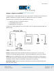
Bit Pad Two 3 Chapter 1: Operation Overview The Bit Pad Two is a data tablet that acts as an input device. It allows for the translation of graphic information into digital, suitable for a digital device such as a computer. The Bit Pad Two is valuable in many applications, including: Steering a cursor on a computer terminal. Picking locations on a menu Digitizing maps, drawings, etc. The parts of a standard Bit Pad Two are the tablet, cursor or stylus, data/power cable and power supply.
Bit Pad Two 4 Power Supply: Source of power for the Bit Pad Two. It attaches to the data/power cable and the power line. Adapter Cables: Cable assemblies that can change the gender of the data/power cable connector; reverse the communication lines or convert the power supply plug to the international standards. The Bit Pad Two translates the position of the stylus or cursor on the tablet into digital information and communicates it to the host. The host is represented by a computer.
Bit Pad Two 5 Reports are in counts of resolution, expressed as absolute coordinates or relative coordinates. Resolution: Smallest distance or movement that the data tablet can distinguish. Resolution is a measure of precision and is expressed in lines per inch (lpi) or lines per millimeter (lpmm). Counts of Resolution: Unit of measure: one count is the distance between two lines of resolution. Absolute coordinates are measured from the tablet’s origin (0, 0).
Bit Pad Two 6 data tablet is in Absolute Mode. Reports are in relative coordinates when the data tablet is in Relative Mode. Absolute and Relative modes are two of the Bit Pad Two’s many operating characteristics. Other operating characteristics govern when reports are issued; how fast they are issued and the tablet resolution. The operating characteristics can be set by commands from the host or by switches. The switches, slide or rocker, are grouped in banks of eight per DIP switch.
Bit Pad Two 7 to report the proximity status. Reports in the ASCII BCD format use the cursor/stylus flag character to identify an out-of-prox report. Section B: Remote Control The data tablet can be configured to accept or reject commands from the host. When the remote control is enabled, the data tablet is receptive to commands from the host.
Bit Pad Two 8 If the switch is set to enable CTS handshaking, the data tablet awaits CTS from the host before it can issue reports. If CTS is not asserted, the data tablet is inhibited from sending reports. If the switch is set to disable CTS handshaking, the data tablet ignores the CTS line. Section E: Hardware Interface The Bit Pad Two has an RS-232C interface. It is full duplex, asynchronous and serial. View the sections below for the pin assignments and signal levels.
Bit Pad Two 9 An adapter cable is available to change the connector gender from female to male.
Bit Pad Two 10 Section F: Report Format and Cursor Output Codes Two report formats are available: packed binary and ASCII BCD. NOTE: To users of other Summagraphics data tablets or digitizers: the formats described here are specific to the Bit Pad Two and Bit Pad One. Other Summagraphics products have similarly named formats, but their content may be different. Regardless of format, reports are in counts of resolution, not in inches or millimeters.
Bit Pad Two 11 LSB Least significant bit MSB Most significant bit PR Proximity, 0 when in proximity and 1 when out-of-prox F Flag bit, identifying the stylus or cursor buttons being pressed. The cursor output codes are switch selective: *On the 3-button cursor, the buttons are distinguished by raised dimples, rather than by numbered labels. In the table above, 1 corresponds to one dimple; 2 to two dimples, etc.
Bit Pad Two 12 PH Phasing bit, which is always 1 P Parity bit SB One or two stop bits X0 to X11 and Y0 to Y11 X and Y coordinate bits. NOTE: In Relative Mode, X11 and Y11 are the sign bits. The bit is 0 for a positive coordinate and 1 for a negative coordinate. Furthermore, the remaining bits for a negative coordinate are in the two’s complement form.
Bit Pad Two 13 *On the 3-button cursor, the buttons are distinguished by raised dimples, rather than by numbered labels. In the table above, 1 corresponds to one dimple, 2 to two dimples and etc. ASCII carriage return ASCII line feed Chapter 3: Guidelines for Writing a Software Driver A computer must have a driver in order for the Bit Pad Two to be connected. The driver is a software subroutine that collets and decodes Bit Pad Two reports for use by another (master) program.
Bit Pad Two 14 General Flowchart for Master Program to Read and Process Data Tablet Reports
Bit Pad Two 15 Detail A: Get and Decode Reports Subroutine
Bit Pad Two 16 Detail B: Data Input Subroutine
Bit Pad Two 17 Chapter 4: Operating Characteristics and Commands Bit Pad Two has a variety of operating characteristics and functions. The operating characteristics control the report flow, report content and tablet resolution. Set the Bit Pad Two’s operating characteristics or initiate the functions with commands from the host or with the switches inside the tablet.
Bit Pad Two 18 Each characteristic or function and its commands are defined. For easy reference, the commands appear in ASCII and hexadecimal. Appendix B ASCII Conversion Chart also provides the binary, decimal and octal conversions. A summary of the commands and switch settings appears in Appendix D Quick Reference Sheet. The command byte format uses the same conventions as those used in the report formats: one start bit, seven data bits, an optional parity bit and one or two stop bits.
Bit Pad Two 19 Switch Setting: Report Rate: DIP #1 Stream Mode: Switch Stream Mode: Please note that one command sets both the mode and Report Rate. However, five switches must be set to accomplish the same setting, two for the mode and three for the Report Rate. Stream Mode Bit Pad Two continuously issues reports. It is not necessary to press a cursor or stylus button.
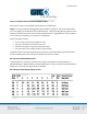
Bit Pad Two 20 Report Rate The Report Rate is the number of reports the data tablet issues each second. Use it with Stream or Switch Stream modes. Note that the Report Rate settings, such as 2 rps or 70 rps, are approximations. The rate at which the data tablet actually sends reports depends on the baud rate and the report format. The following tables identify the rates you can expect.
Bit Pad Two 21 Point Mode Command: Switch Setting: In Point Mode, the Bit Pad Two issues one report each time a cursor or stylus button is pressed. Reports can be issued up to the maximum Report Rate available for the set baud rate. Remote Request Mode Command: Switch Setting: In Remote Request Mode, the Bit Pad Two issues one report each time the host sends a trigger command. Issue the mode command once. Thereafter, send only a trigger command for each report.
Bit Pad Two 22 In Absolute Mode, the Bit Pad Two issues reports as absolute coordinates. Absolute coordinates are measured relative to the tablet origin. Reports issued from out-of-prox are repeats of the last valid coordinate pair. NOTE: When reports are in binary format and the data tablet is in Absolute Mode, the maximum reportable value is 4095. (Reports in ASCII BCD format have no restrictions.) Reports larger than this are detailed as the maximum value (4095).
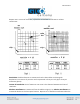
Bit Pad Two 23 The effect is a restriction of the maximum delta between reported points. The delta is the distance from the last report to the current one. The maximum delta varies, depending on the tablet’s resolution setting. This relationship is quantified in the table below: Increment Mode Command: Switch Setting: In Increment Mode, the Bit Pad Two sends a report only when the cursor or stylus has traveled a minimum distance in the X or Y direction. This minimum distance is the increment.
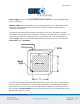
Bit Pad Two 24 Here’s a description of how Increment Mode works: last report issued becomes the center of an imaginary square whose sides are twice the increment value. The cursor can move anywhere inside the imaginary square without a report being issued. As soon as the increment is satisfied along either axis, the Bit Pad Two transmits the actual X and Y coordinates of the point. The new point becomes the center of a new, imaginary square.
Bit Pad Two 25 4 (30,7) The increment is satisfied from the last point along the X axis only; the Bit Pad Two issues the new report. 5 (32,17) The increment is satisfied from the last point along the Y axis only; the Bit Pad Two issues the new report. Section B: Combining Characteristics This section describes some of the nuances of combining primary modes and modifiers. Reports are not issued in response to buttons being pressed when the data tablet is in Remote Request Mode.
Bit Pad Two 26 When the data tablet is in Remote Request and Increment modes, regardless of whether the increment has been satisfied or not, the actual position where the stylus or cursor is when the data tablet receives the remote trigger is reported position. If Point or Remote Request modes are set by switch rather than by command, the Report Rate, also set by switch, is valid. Consequently, the Report Rate has priority over buttons or remote triggers.
Bit Pad Two 27 Send Configuration Command: Switch Setting: Use the Send Configuration command to send a report to the host that identifies the data tablet model and its version of software. The output looks like this: MM1103_BIT_PAD_II_by_Summagraphics_Version_n.n The underlines are spaces; n.n is the version number and the line feed is switch-selective.
Bit Pad Two 28 The data tablet will respond to other commands, such as a command to change the resolution, while it is on standby. If the Reset command is issued while the data tablet is on standby, the data tablet honors the Reset command, but does not retract the XOFF state. Reset Command: Switch Setting: Use the Reset command to return the operating characteristics to their current switch settings.
Bit Pad Two 29 Chapter 5: Checking the Data Tablet A convenient functional check of the data tablet can be performed by connecting Bit Pad Two to a terminal and moving the cursor or stylus across the tablet’s active area. (The output is easier to interpret if you have the report format set for ASCII BCD.) The X and Y values should increase as the cursor or stylus slides from the tablet origin toward the end of the axis.
Bit Pad Two 30 Section A: Self-Test Diagnostic Function Command: Switch Setting: Use the Self-Test command to perform tests on the tablet and cursor or stylus. Self-Test checks: Analog circuitry Cursor or stylus connection, operation and location Digital circuitry After the test is performed, the results are sent to the host.
Bit Pad Two 31 If the Self-Test output byte is an ASCII O or G, the data tablet passed the diagnostic tests. (An O simply indicates that the stylus/cursor is in proximity. A G indicates that it is out-ofprox.) Section B: In Case of Failure If the Bit Pad Two does not operate or fails the Self-Test, follow these steps: 1. Power down the Bit Pad Two. 2. Check that cables are firmly attached. 3. Ensure that the host is working properly. 4. If possible, issue each diagnostic command and review the results.
Bit Pad Two 32 Power The power supply shipped with Bit Pad Two provides the proper power: 300mA at +12VDC with +/-.5% regulation or better and 100 mA at -12VDC with +/-5% regulation or better. Section B: Unpacking and Installation Unpacking Immediately upon receipt, inspect the package for damage. If damage exists: 1. Open the package and inspect the damage. 2. Report the damage to the carrier as soon as possible, preferably within 72 hours or receipt. 3. Record the damaged items on the freight bill. 4.
Bit Pad Two 33 Installation A brief summary of the steps for assembling and installing a Bit Pad Two is as follows: 1. Configure Bit Pad Two data tablet. 2. Adjust the tilt or use flat 3. Attach stylus holder, if applicable. 4. Connect the stylus or cursor to the tablet. 5. Attach the tablet to the host. 6. Connect the tablet to the power source.
Bit Pad Two 34
Bit Pad Two 35 1. Configure Bit Pad Two Data Tablet The Bit Pad Two’s configuration parameters are set at the factory to your specifications. If however, you want to adjust the configuration, you can do so by setting the switches inside the tablet. It is advantageous to do this step before connecting the unit with the host since it requires disassembling the tablet.
Bit Pad Two 36 The ON and OFF positions are labeled on each switch. Set a slide switch by sliding it to the desired position. Set a rocker switch by pressing down on the side next to the desired position. Use a pointed instrument. Do NOT, however, use a pencil or another instrument that could deposit residue, e.g. graphite or ink, on the switch. This could cause the switch to malfunction. 2. Adjust the Tilt or Use Flat Bit Pad Two can tilt or lie flat.
Bit Pad Two 37 Lift the tilt mounting gently to clear the cursor/stylus socket. Remove the tilt assembly. Remove the paper backing from the rubber feet. Stick the feet on the tablet back, approximately one inch from each corner. 3. Attach Stylus Holder (if applicable) Attach the stylus holder anywhere along the tablet edge within five inches from the tablet top. Refer to the illustration below: Remove the protective paper from the adhesive tape. Attach the taped side to the back of the tablet. 4.
Bit Pad Two 38 5. Connect the Tablet to the Host The RS-232C cable is equipped with a 25-pin female D connector with a jack screw. The host must have a 25-pin male D connector (AMP P/N 205208-1). To lock the connectors together, the host connector must have a screw lock (AMP P/N 2058171). If the system requires them, adapter cables are available to change the connector gender from female to male; or to reverse communication lines. Install an adapter cable between Bit Pad Two data/power cable and the host.
Bit Pad Two 39 Section C: FCC Considerations As stated by FCC rules and regulations, Bit Pad Two must be installed and operated in accordance with the procedures appearing in this manual. In addition, to ensure that EMI shielding requirements are met, the host’s interface cabling connector must have a metal shroud, grounded to the host chassis. Section D: Care and Cleaning Avoid sharply banging or dropping the tablet, cursor or stylus. Never immerse any part in fluid.
Bit Pad Two 40 Appendix A: Specifications Physical Description Overall Dimensions 16.0” x 16.2” x 0.80” 406mm x 412mm x 20mm Active Area (nominal) 11” x 11” 280mm x 280mm Weight Maximum: 7 pounds 3.2kg Power Requirements 300 mA at +12VDC with +/-.5% regulation or better and 100 mA at -12VDC with +/-5% regulation or better. Optional Power Supplies U.S.A. International Japan 102V to 132V; 58Hz to 62Hz; NEMA 5-15P plug 197V to 264V; 48Hz to 52Hz; I.E.C.
Bit Pad Two 41 Accuracy The similarity of a distance measured by the tablet with the actual distance. Cursor Eccentricity How much the electrical center varies from the crosshair center as the cursor is rotated through 360 degrees. Jitter Repeatability error of short duration caused by electrical noise. Proximity Greatest distance above the drawing area that the pointing tool can be raised and still be sensed by the tablet.
Bit Pad Two 42 Appendix B: ASCII Conversion Chart
Bit Pad Two 43
Bit Pad Two 44
Bit Pad Two 45 Appendix C: How the Bit Pad Two is Different from Bit Pad One Bit Pad Two is a second generation data tablet. It is, with some minor exceptions, a plug replacement for Bit Pad One. As an improved version of its predecessor, dissimilarities do exist. For example, the Bit Pad Two uses more advanced hardware and different technology. Some noteworthy exceptions regarding Bit Pad Two: Does not require biasing: pulling a magnet over the tablet.
Bit Pad Two 46 Switch Settings: DIP Switch 1
Bit Pad Two 47 Switch Settings: DIP Switch 3
Bit Pad Two 48 Corporate Headquarters 14557 N. 82nd Street Scottsdale, Arizona 85260 Tel: 1-866-746-3015 Support: 1-866-746-3015 Fax: 480-998-1751 Support: 1.866.746.3015 Copyright© 2014 GTCO CalComp by Turning Technologies, Inc. Bit Pad Two is a trademark of GTCO CalComp by Turning Technologies, Inc. All other products and company names are the trademarks or registered trademarks of their respective owners. The information contained in this document is subject to change without notice.