SmartCell Repeater User Manual 33 dBm July, 2012 Version 1.
User Manual SmartCell Repeater - INDEX 1. INTRODUCTION .............................................................................................................3 1.1 GST SmartCell Repeater Advantages ...........................................................................5 1.2 Abbreviation.................................................................................................................5 2. SYSTEM CONFIGURATION ............................................................................
User Manual SmartCell Repeater U.S.A. U.S.FEDERAL COMMUNICATIONS COMMISSION RADIO FREQUENCY INTERFERENCE STATEMENT INFORMATION TO THE USER NOTE: This equipment has been tested and found to comply with the limits for a Class A digital device, pursuant to Part 15 of the FCC Rules. These limits are designed to provide reasonable protection against harmful interference when the equipment is operated in a commercial environment.
User Manual SmartCell Repeater IC Warning This device complies with Industry Canada licence-exempt RSS standard(s). Operation is subject to the following two conditions: (1) this device may not cause interference, and (2) this device must accept any interference, including interference that may cause undesired operation of the device. Le présent appareil est conforme aux CNR d'Industrie Canada applicables aux appareils radio exempts de licence.
User Manual SmartCell Repeater 1. INTRODUCTION SmartCell is a modular repeater designed to improve signals in blanket/shadow areas inside buildings. It can transmit signals at 700MHz, 850MHz, 1900MHz, and 2100MHz frequencies. User may choose filtering configurations according to the specific site’s requirements. 1.1 GST SmartCell Repeater Advantages It provides selectable RF power levels for any wireless technology / band. It provides monitoring for multiple technologies.
User Manual SmartCell Repeater CAUTION THIS EQUIPMENT IS INDOOR USE ALL THE COMMUNICATION WIRINGS ARE LIMITED TO INSIDE OF THE BUILDING RISK OF EXPLOSION IF BATTERY ON CONTROLLER BOARD IS REPLACED WITH AN INCORRECT TYPE. DISPOES OF USED BATTERIES ACCORDING TO THE INSTRUCTIONS. THE SOCKET-OUTLET SHALL BE INSTALLED NEAR THE EQUIPMENT SHALL BE EASILY ACCESIBLE. THIS POWER OF THIS SYSTEM SHALL BE SUPPLED THROUGH WIRING INSTALLED IN A NORMAL BUILDING.
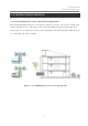
User Manual SmartCell Repeater 2. SYSTEM CONFIGURATION 2.1 SmartCell Repeater Service Network Configuration The SmartCell Modular Repeater is designed to improve coverage and capacity of LTE, PCS, Celluar, and AWS services. The repeater can provide in building coverage for all trouble areas. SmartCell is easy to install, has remote status monitoring and control functions (NMS System) via a wired line and wireless modem.
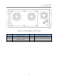
User Manual SmartCell Repeater 2.2 System Design and Operation 2.2.1 System Design 1 7 2 3 4 5 6 17 13 8 15 9 16 10 14 11 12 SmartCell Repeater Front Design NO. PART NO.
User Manual SmartCell Repeater 2 4 1 3 5 SmartCell Repeater Back Design NO. PORT NO.
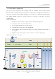
User Manual SmartCell Repeater 2.2.2 Downlink/ Uplink Path The user may select frequency bands according to the site conditions. After receiving a signal from the donor antenna(s), the repeater improves it and sends a securely isolated signal out to the service antenna(s). Each amplifier module has its own separate digital filter module (DFM). The amplifier module consists of a down converter, up converters, cavity filter, and power amplifier (PAU). In the Downlink Path: 1.
User Manual SmartCell Repeater 2.2.3 700MHz Frequency Selection 700MHz Band Frequency The 700MHz AMP module complies with LTE 3GPP requirements, where a maximum of two noncontiguous block configurations are available. Each block is adjustable per 5 MHz. 2.2.4 850MHz Frequency Selection 850MHz Band Frequency The 850MHz AMP module provides Cellular service, where a maximum of two non-contiguous block configurations are available.
User Manual SmartCell Repeater 2.2.5 1900MHz Frequency Selection 1900MHz Band Frequency The 1900MHz AMP module complies with PCS Band blocks, where a maximum of three noncontiguous filtering configurations are available. Each sub block is adjustable per 1.25MHz bandwidth steps up to 20MHz. The Following table shows user selectable channel numbers. DL CENTER [MHz] CHANNEL BAND DL CENTER [MHz] CHANNEL 1931.25 25 guard 1965 700 A1 1932.5 1933.75 50 75 E 1966.25 1967.
User Manual SmartCell Repeater 2.2.6 2100MHz Frequency Selection F1 F2 2100MHz Band Frequency The 2100MHz AMP module complies with CDMA band requirements, where two block configurations are available. In order to set contiguous band F, check ‘Band F1’, ‘Band F2’ and ‘contiguous’ button in the WEB UI. In order to set Band F1 or Band 2 do not check ‘contiguous’ button in WEB UI. Band F configuration is as follows: Downlink BAND F Uplink Start Stop Start Stop F1 2145.15 2149.85 1745.
User Manual SmartCell Repeater 3. SETUP 3.1 Equipment Needed for Repeater Setup Parameter Item Quantity Remark Major Component SmartCell Repeater 1 EA Provided by GST Wall Mounting Bracket 1 EA CD which contains User Manual 1 EA and Installation Guide Additional Components Antenna RF Cable Testing and Measuring Equipment Ethernet Cable 6.6ft (2m) 1 EA Ground Cable 6.6ft (2m) 1 EA Ground Sems Screw M4 x 8mm 4 EA Bracket Sems Screw M5 x 10mm 20 EA Lag Screw 12.7mm x 50.
User Manual SmartCell Repeater 3.1.2 Ready for Service 1. Check points before Service: a. Verification of system installation: - Electricity, In/Out antennas, cable connections, and equipment mounting. b. Verification of system accessories: - User should check all necessary accessories. c. Check received signal level: - User should check whether environmental conditions are in accordance with system specifications to ensure the system operation will be optimized. 2. Check points after Service: a.
User Manual SmartCell Repeater 3.2.1 Quick GUI/Configuration Use the following steps to commission the Repeater after all the cabling and antennas are fixed in place and the Repeater is supplied with proper electrical power. The repeater will need a stable Downlink RSSI input level in the range of -85dBm to -60dBm. 1. Connect your laptop to the LAN port on the repeater with a Crossover Ethernet cable. 2.
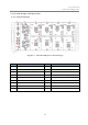
User Manual SmartCell Repeater Control Gain Balance Control Gain Balance Value Shutdown Control Auto Gain Setting Auto Oscillation Control Temperature Display AMP Temperature Upper Limit Band Blocks Used/Bandwidth On/Off 0dB to 15dB On/Off On/Off On/Off 32 to 260.
User Manual SmartCell Repeater us Output Power Downlink Do nor power to o low Input RSSI from Dono r site is 8dB less than Downlink Low Input Li mit Downlink VS WR When the VSWR Ratio on the Server Port is greater than 3 : 1 Downlink Do nor power to o high Downlink Input Power is greater than 25dBm Downlink Syn Failure of the thesizer failur synthesizer Downlink e path Downlink Int erfere power exceeded Uplink Out of band emissi ons out of sp ec Uplink Power at coverage port too high Uplink Synth e
User Manual SmartCell Repeater use. * Move the closest indoor service antenna farther away from the outside Donor antenna. * Close the repeater door if opened and verify that the closest indoor coverage antenna is not in the same roo m as the repeater.
User Manual SmartCell Repeater 3.4.
User Manual SmartCell Repeater problem In case of dropped call or bad signal after set up In case output Signal wavelength is not shown flat or looks like oscillation -Technician should connect antenna with -Reconnect the connector output port of repeater -Change it if the connector is defective -Make sure all connectors are fastened -Increase output power or check input change of Check the input level BTS side -If the Gain is different from normal level, please Check gain of the unit contact GST’s Techn
User Manual SmartCell Repeater 3.4.
MPE Information Warning: Exposure to Radio Frequency Radiation The radiated output power of this device is far below the FCC radio frequency exposure limits. Nevertheless, the device should be used in such a manner that the potential for human contact during normal operation is minimized. In order to avoid the possibility of exceeding the FCC radio frequency exposure limits, human proximity to the antenna should not be less than 50 cm during normal operation. The gain of the antenna is 9.0 dBi.