Smart-Cell Repeater User Manual 33dBm April, 2016 Version 1.
Verizon User Manual Smart-Cell Repeater - INDEX 1. INTRODUCTION .......................................................................................................................... 4 1.1. Warning .................................................................................................................................................................................... 4 1.1.1 FCC Warning Statements ............................................................................................
Verizon User Manual Smart-Cell Repeater 4.2.1. Quick GUI/Configuration .....................................................................................................................................24 4.2.2. Quick Setup ................................................................................................................................................................24 4.3. Web UI Ranges Table..............................................................................................
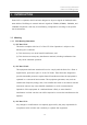
Verizon User Manual Smart-Cell Repeater 1. INTRODUCTION Smart-Cell is a repeater, which has been designed to improve signals in blanket/shadow areas inside of buildings to transmit Verizon’s signals at 700MHz, 850MHz, 1900MHz, and 2100MHz frequencies. User may choose filtering configuration according to the specific site circumstances. 1.1. Warning 1.1.1 FCC Warning Statements 1) FCC Part 15.19 : This device complies with Part 15 of the FCC Rules.
Verizon User Manual Smart-Cell Repeater 4) FCC Part 27.5, IC SRSP-518 Antennas must be installed in accordance with FCC 27.50 and SRSP 518. Please note that EIRP based on antenna gain after accounting for cable loss should be less than 50 Watt (47 dBm) for Donor side. For Service side, with 2dBi gain antennas the height of the antenna above average terrain (HAAT) must not exceed 14.496 m. For different gain antennas refer to the relevant rules. 5) FCC Warning Label WARNING. This is NOT a CONSUMER device.
Verizon User Manual Smart-Cell Repeater 1.1.2. IC Warning state 1) RSS-GEN, Sec. 7.1.2 – (transmitters) Under Industry Canada regulations, this radio transmitter may only operate using an antenna of a type and maximum (or lesser) gain approved for the transmitter by Industry Canada. To reduce potential radio interference to other users, the antenna type and its gain should be so chosen that the equivalent isotropically radiated power (e.i.r.p.) is not more than that necessary for successful communication.
Verizon User Manual Smart-Cell Repeater by 3.5 dB, especially where the output signal is re-radiated and can cause interference to adjacent band users. This power reduction is to be by means of input power or gain reduction and not by an attenuator at the output of the device." 4) RF Radiation Exposure This equipment complies with RF radiation exposure limits set forth for an uncontrolled environment.
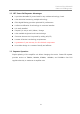
Verizon User Manual Smart-Cell Repeater 1.2. GST Smart-Cell Repeater Advantages It provides selectable RF power levels for any wireless technology / band. It has individual monitoring multiple technology. FPGA digital filtering provides optimized RF performance. It allows modification of technology via customer interface. It is easily installed. Frequency is easy to add / delete / change. It has scalable single and multi-service design.
Verizon User Manual Smart-Cell Repeater 1.4. Abbreviation DFM Digital Filter Module PSU Power Supply Unit ALC Auto Level Control SNMP AOC Simple Network Management Protocol Auto Oscillation Check Caution: Risk of explosion if battery on the controller board is replaced by an incorrect type.
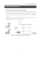
Verizon User Manual Smart-Cell Repeater 2. SYSTEM CONFIGURATION 2.1. Smart-Cell Repeater Service Network Configuration Smart-Cell RF Repeater is designed for improving coverage and capacity of Verizon’s LTE & CDMA services nationwide. The repeater can provide coverage for all troubled areas such as suburban, shadow areas, backside of mountains, urban and metropolitan locations.
Verizon User Manual Smart-Cell Repeater 2.2. System Design and Operation 2.2.1. System Design Smart-Cell Repeater Front Design NO. PART NO.
Verizon User Manual Smart-Cell Repeater 2 4 1 3 5 Repeater Port Design (Rear View) NO. PORT NO. PORT 1 Main FAN 4 DC 12V output (for EMB) 2 PSU FAN 5 Power Cable 3 Main Switch 2.2.2. Downlink/ Uplink Path The Smart-Cell repeater improves service in the 700MHz, 800MHz, 850MHz, 1900MHz and 2100MHz frequency bands. User may select frequency band according to the site peculiarities.
Verizon User Manual Smart-Cell Repeater Smart-Cell Repeater Block Diagram 2.2.3. 700MHz Frequency Selection (LTE) Smart-Cell Repeater 700 Block Diagram 700MHz Amp Unit provides a service that meets the 3GPP2 LTE standard. Support up to two non-contiguous blocks. And each block has the minimum 5MHz bandwidth.
Verizon User Manual Smart-Cell Repeater 2.2.4. 800MHz Frequency Selection (iDEN) Smart-Cell Repeater 800 Block Diagram 800MHz Amp Unit has service Cellular 1FA and provides LTE 5MHz (25RB) by default. On / Off control of the service Block is possible. Each block‘s bandwidth are as follows. (CDMA[UL] – 1.25MHz, LTE[UL] – 4.505MHz, CDMA[DL] – 1.25MHz, LTE[DL] – 4.505MHz) 2.2.5.
Verizon User Manual Smart-Cell Repeater DL CENTER BAND guard A2 guard A3 guard D guard B1 guard B BAND 1931.25 25 guard 1932.5 50 1933.75 75 1935 100 1936.25 125 1937.5 150 1938.75 175 1940 200 1941.25 225 1942.5 250 1943.75 275 1945 300 1946.25 325 1947.5 350 1948.75 375 1950 400 1951.25 425 1952.5 450 1953.75 475 1955 500 1956.25 525 1957.5 550 1958.75 575 1960 600 1961.25 625 1962.5 650 1963.
Verizon User Manual Smart-Cell Repeater 2.2.7. 2100MHz Frequency Selection (AWS) F1 F2 2100MHz Band Frequency 2100 Amp Unit has basically satisfies the CDMA standard, and supports non-contiguous 2 block. If you select “contiguous button”, Web UI has select the contiguous F band. And you don’t select “Contiguous button”, Web UI has select the each band of F1 and F2. Frequency range of each band as follows. Downlink BAND F Uplink Start Stop Start Stop F1 2145.15 2149.85 1745.15 1749.
Verizon User Manual Smart-Cell Repeater 3. SYSTEM SPECIFICATIONS 3.1. RF Performance Item Specification Remark DL : 728.5MHz ~ 739.5MHz 700MHz 746MHz ~ 756MHz UL : 698.5MHz ~ 709.5MHz 5MHz / 10MHz 777MHz ~ 787MHz DL : 862MHz ~ 863.8MHz 800MHz Frequency 864MHz ~ 868.6MHz UL : 817MHz ~ 818.8MHz 1.8MHz + 4.8MHz 819MHz ~ 823.
Verizon User Manual Smart-Cell Repeater 3.2. System Specifications Parameter Gain Specification Range 60dB ~ 90dB Adjust Step ±0.5dB Adjust Accuracy ±1dB 700MHz < 3.0dBp-p 800MHz Flatness Remark 850MHz 1900MHz < 5.0dBp-p 2100MHz Propagation Delay ≤ 6us VSWR Noise Figure 1.7 : 1 Max Gain < 7dB 750MHz 45dBc @±5MHz/10MHz > 45 dBc ±750KHz >50dBc@±1.98KHz 800MHz 45dBc @±5MHz/10MHz > 45 dBc ±885KHz ACP 850MHz >52dBc@±1.98KHz <-13dBm@Fc±2.
Verizon User Manual Smart-Cell Repeater 3.3. Electrical and Environmental Specifications Item Specification Remark RF Connector N-Type Female Donor & Server ANT Port AC Supply AC 110V 60Hz 3.0A Out Dimension Weight 3.1” x 15.5” x 7.7” AMP unit 19” x 19” x 7.9” System (Rack mount) 13lbs 700 unit 11.5lbs 850 unit 11.
Verizon User Manual Smart-Cell Repeater • 2100MHz: 5MHz/10MHz Power Monitoring • Monitoring repeater’s output level. • Isolation Check in initial set up or Reset. • When Oscillation occurred, repeater attempts to stabilize Isolation through Gain Oscillation Check control function. • Shutdown repeater when oscillation still occurs in the minimum Gain. • Automatic Recovery Algorithm conversion after shutdown status.
Verizon User Manual Smart-Cell Repeater 4. SETUP 4.1. Equipment Needed for Repeater Setup Parameter Item Quantity Remark Major Component Smart-Cell Repeater 1 EA Provided by GST WALL Mounting Bracket 1 EA CD which contains User Manual 1 EA V.1.0 and Installation Guide V.1.0 Additional Components Ethernet Cable 6.6ft (2m) 1 EA Ground Cable 6.6ft (2m) 1 EA Ground Sems Screw M4 x 8mm 4 EA Bracket Sems Screw M6 x 10mm 4 EA Lag Screw 12.7mm x 50.
Verizon User Manual Smart-Cell Repeater 3) Isolation check between DONOR/SERVEICE ANT ① Isolation condition of this equipment is 105dBc (Gain+15dB). User should check its condition before installation. 4.1.2. Open for Service 1) Check points before open: ① Verification of system installation status : Electricity, In/Out antennas, cable connection, and equipment mount status. ② Verification of system accessories : User should check all necessary accessories.
Verizon User Manual Smart-Cell Repeater 4.1.3.
Verizon User Manual Smart-Cell Repeater 4.2. Setting up the Repeater 4.2.1. Quick GUI/Configuration Use the following steps to commission the Repeater after all the cabling and antennas are fixed in place and the Repeater is supplied with proper electrical power. The repeater will need a good quality stable Downlink RSSI input level in the range of 85dBm to -60dBm. 1) Connect your laptop to the repeater with a Crossover Ethernet cable.
Verizon User Manual Smart-Cell Repeater 4.3.
Verizon User Manual Smart-Cell Repeater 4.4. Troubleshooting In case of abnormal operation, technician should diagnose abnormality via remote access or directly connecting to repeater using Ethernet cable. If technician is required to conduct repairs due to major alarm, repeater should first be powered off, and then technician should prepare the proper measurement equipment before trying to fix the problem.
Verizon User Manual Smart-Cell Repeater Downlink Downlink path gain is Hardware 6dB less than RSSI failure plus Output Power Downlink Input RSSI from Donor Donor site is 8dB less too than Downlink Low power Input Limit low When the VSWR Downlink Ratio on the Server VSWR Port is greater than 3:1 Downlink Downlink Input Donor power too high Power exceeds 25dBm * By default, if the Downlink Low Output Variance is set to 10dB, the Repeater will not report this alarm.
Verizon User Manual Smart-Cell Repeater the Uplink Upper Limit on the RF Configuration Page. * Add equal amounts of Uplink and Downlink attenuation until the Uplink Output Power is less than the Uplink Upper Limit.
Verizon User Manual Smart-Cell Repeater * Close the repeater door if opened and verify that the closest indoor coverage antenna is not in the same room as the repeater. Field Replaceable module Filter service has not matches between Amp Unit and DFM failure Tamper Detected * Call to GST's Tech Support Team to verify that all the settings are correct. When mount * After 5 minutes clear automatically.
Verizon User Manual Smart-Cell Repeater 4.4.3.
Verizon User Manual Smart-Cell Repeater Please Check following status; DL VSWR alarm -Make sure Server Antenna Port is disconnected.
Verizon User Manual Smart-Cell Repeater Check gain of the unit -If the Gain is different from normal level, please contact A/S team -It is possible for connectors to get too tight and Cable connector loose damage the equipment or throughput -Please contact installer or service provider upon verification Check input signal strength in the service In case of dropped call or bad signal after set up area -Increase output power level of repeater by adjusting attenuation level If input signal strength is
Verizon User Manual Smart-Cell Repeater 4.4.4.