Technicians Installation & Operation Guide Model: SMR-IP10-D SMR-IP10-S Version 1.0 Confidential and proprietary to GS Teletech Inc. Copying, reproduction or distribution this information is strictly prohibited without prior written authorization from GST. GS Teletech Inc.
Technician’s Installation & Operation Guide SMR-IP10 SMR-IP10-D/-S Smart Mobile Repeater for 800MHz and 1900MHz Bands Application: Small Business, Enterprise and Public venues. Coverage: Up to 5k sq. ft. per unit.
Technician’s Installation & Operation Guide SMR-IP10 This publication provides instructions for installing the 800MHz and 1900MHz Smart Mobile Repeater. The images for the User Interface in this publication may vary depending on it’s S/W version. Copyright © 2015, GS Teletech, Inc. All Rights Reserved Printed in the Republic of Korea Version History: Date Version 04/2015 1.
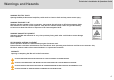
Technician’s Installation & Operation Guide Warnings and Hazards WARNING! ELECTRIC SHOCK Opening the BDA (bi-directional amplifier) could result in electric shock and may cause severe injury. WARNING! EXPOSURE TO RF Working with the repeater while in operation, may expose the technician to RF electromagnetic fields that exceed FCC rules for human exposure. Visit the FCC website at http://www.fcc.gov/oet/rfsafety to learn more about the effects of exposure to RF electromagnetic fields.
Technician’s Installation & Operation Guide Warnings and Hazards This equipment has been tested and found to comply with the limits for a Class B digital device, pursuant to part 15 of the FCC Rules. These limits are designed to provide reasonable protection against harmful interference in a residential installation.
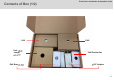
Technician’s Installation & Operation Guide Contents of Box (1/2) SAU Link Cable Jumper AC Cord DAU Bracket Set DAU SAU Bracket Set AC/DC Adaptor 6
Technician’s Installation & Operation Guide Contents of Box (2/2) No 1 2 Item Donor Antenna Unit (DAU) Service Antenna Unit (SAU) Q-ty 1 Picture No 7 1 8 3 4 Link cable (1.
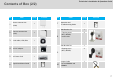
Technician’s Installation & Operation Guide Repeater Design SMR-IP10-D Donor Antenna Unit (DAU) SMR-IP10-S Service Antenna Unit (SAU) 8
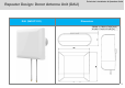
Technician’s Installation & Operation Guide Repeater Design: Donor Antenna Unit (DAU) DAU (SMR-IP10-D) Dimensions 209(W) X 190(H) X 74(D) [mm] 8.2(W) X 7.4(H) X 2.
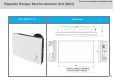
Technician’s Installation & Operation Guide Repeater Design: Service Antenna Unit (SAU) SAU (SMR-IP10-S) Dimensions 252(W) X 148(H) X 54(D) [mm] 9.9(W) X 5.8(H) X 2.
Technician’s Installation & Operation Guide 800MHz & 1900MHz Frequency Bands Service Band Blocks 1900MHz Band A D E B F C 1850 800MHz Band 1910 1915 CDMA 817 G A F C 862 G 1990 1995 CDMA 824 E B 1930 LTE 819 D LTE 864 869 11
Technician’s Installation & Operation Guide Introduction The SMR-IP10 is a paired repeater solution consisting of a Donor Antenna Unit (DAU) and a Service Antenna Unit (SAU). The SMR-IP10 can be installed with a maximum of 4 service antennas using external antenna ports. The installer should consider a link budget from the SAU to Service Antennas while using external antennas and dividers (splitters).
Technician’s Installation & Operation Guide Installation Guideline Donor Antenna Unit (DAU) The Donor Antenna Unit (DAU)’s position is very important to receive clear and stable signals from the base station. Find a location where the RF signal is the most stable and install the DAU.
Technician’s Installation & Operation Guide Installation Guideline Service Antenna Unit (SAU) The Service Antenna Unit (SAU) shall be positioned in the direction of target service area. Secure enough distance between the Donor Antenna Unit and the Service Antenna Unit to prevent oscillation. Install the SAU on the wall or ceiling. Install the SAU in a location where people cannot easily reach. Secure isolation over 10ft between antennas if you install SAU near other carrier antennas.
Technician’s Installation & Operation Guide Installation Guideline Application Donor Antenna Unit Divider (Splitter) Service Antenna Unit Service Antenna Basic Structure (Recommended) Link Cable Loss consideration is necessary if extended Built-in antenna 1 External Antenna Link Cable Loss consideration is necessary if extended Cable Loss should be considered 2 External Antenna Cable Loss should be considered Link Cable Loss consideration is necessary if extended 15
Technician’s Installation & Operation Guide Installation Guideline When using 4 dividers, the following architecture will be applicable and the divider shall stay the same.
Technician’s Installation & Operation Guide Installation Guideline Coverage Area – CDMA 1X RSSI The expected line of sight coverage area is shown below. The total loss of service includes cable losses and divider losses. The following table shows Uplink coverage. The downlink coverage is wider than the Uplink coverage. For example, when the input signal level of Donor Antenna Unit (DAU) is -90dBm and coverage is 15m, the total loss of service side is necessary to make less than 15dB.
Technician’s Installation & Operation Guide Installation Guideline Coverage Area - LTE The Downlink and Uplink throughput shall be measured at over 80% of outdoor throughput measurement.
Technician’s Installation & Operation Guide Installation Guideline Link cable Cable Length: 50m (164 ft.
Technician’s Installation & Operation Guide Installation Guideline Link Cable Extension DC Drop: No Problem (AC/DC Adaptor (DC Source): +19V) for below cables Cable Loss range: 9dB ~ 15dB (Mandatory) [Strongly recommended] Cable Type Link Distance Remark 1/8 inch Coaxial Cable 50m (164ft) ~ 100m (328ft) Approximately 1/4 inch Coaxial Cable 100m (328ft) ~ 180m (590ft) Approximately 3/8 inch Coaxial Cable 180m (590ft) ~ 270m (885ft) Approximately 3/8 ” 1/4” 1/8” Coaxial Cable(50 ohm) Coaxial
Technician’s Installation & Operation Guide Measurement Criteria Site Survey (Roof): Conditions for DAU Positioning Site Survey (Roof) 1x CDMA 800 MHz 1900 MHz PN Serving Physical Cell Identity RSSI (dBm) -95dBm or above -95dBm or above Ec/Io (dB) -12dB or above -12dB or above EVDO 800 MHz 1900 MHz Serving Physical Cell Identity PN N/A RSSI (dBm) N/A -95dBm or above Ec/Io (dB) N/A -12dB or above Serving Physical Cell Identity LTE 800 MHz 1900 MHz PCI Serving Physical Cell Ident
Technician’s Installation & Operation Guide Measurement Criteria Site Survey (Target Area): Conditions for SAU Positioning SMR-IP10 shall be installed even if one of the following 1x CDMA, EVDO and LTE criteria's are satisfied .
Technician’s Installation & Operation Guide Measurement Criteria Post-installation (Service Area): Measurement Condition: More than 80% of coverage area Post-Installation Measurements (Retail/Sales Area) 1x CDMA 800 MHz 1900 MHz PN Serving Physical Cell Identity RSSI (dBm) -85dBm or above Serving Physical Cell Identity -85dBm or above Ec/Io (dB) -10dB or above -8dB or above Mobile TX power EVDO 0dBm or less 800 MHz 1900 MHz PN N/A Serving Physical Cell Identity RSSI (dBm) N/A -85dBm or
Technician’s Installation & Operation Guide Cable Connections Link Cable Ports CAUTION Do not connect or disconnect cable from ANT port when power is ON.
Technician’s Installation & Operation Guide Repeater Port Design Donor Antenna Unit 1 2 [DAU Bottom Side] No Port Connector 1 Link Cable Port SMA (F) 2 800MHz Antenna Port (If required) SMA (F) 2 Both 800MHz and 1900MHz Antenna Port (if extremely required) SMA (F) In special cases, the DAU’s EXT.ANT can be connected with a high gain antenna for both 800MHz and 1900MHz. Please refer to page 32 for ‘Jumper connection’ in this document, and it shall be confirmed and approved by GST.
Technician’s Installation & Operation Guide Repeater External Port Design Service Antenna Unit External Antenna Port WebGUI (RJ45) Link Cable Connection Power On / Off LED Indicator LED Indicator (Power / Alarm) (Band Information AC/DC Adaptor & Signal Strength) [Left Side] [Bottom Side] [Right Side] 26
Technician’s Installation & Operation Guide Setup Start Link Cable Connection Locate the DAU & SAU positions AC/DC Adaptor Connection Input Signal Checking SAU Switch On NO More than -95dBm YES Start ‘WebGUI’ Band Selection & Alarm Check DAU Mounting Check LED Status Link Cable Connection Cabling to SAU Finish SAU Mounting AC outlet construction 27
Technician’s Installation & Operation Guide Positioning of DAU Search for the proper BTS location Please refer to ‘Measurement Criteria’ .
Technician’s Installation & Operation Guide Mounting SMR-IP10 Donor Antenna Unit (DAU) 1. Find a location which provides good LTE signals from the Base Station. 2. Using a pencil, mark the location of each of the DAU Bracket’s four mounting holes on the wall. 3. Drill holes in the wall at the locations marked in step 1. 4. Set the anchors in the wall, position the bracket, and tighten tapping screws until secured. 5. Put the DAU into mounting bracket. 6. Tighten the mounting bracket with a wrench (32 mm).
Technician’s Installation & Operation Guide Mounting SMR-IP10 Installed DAU Example. The DAU should be installed pointing toward a Base Station to receive clear and stable CDMA/LTE signals.
Technician’s Installation & Operation Guide External Antenna Installation for 800MHz. GS Teletech, Inc. If required Installed DAU and 800MHz External antenna ※ Depending on Base Station’s location for both 800MHz and 1900Mhz.
Technician’s Installation & Operation Guide External Antenna Installation for 800MHz. If required Installed DAU and 800MHz External antenna The external antenna should be positioned toward the Base Station (BTS) from individual BTS site for both 800MHz and 1900MHz network.
Technician’s Installation & Operation Guide Upgrading Existing Repeater With SMR-IP10 For replacing an existing repeater If necessary Jumper cable connection for adapting both 800MHz and 1900MHz The Dual band antenna port for both 800MHz and 1900MHz should be connected with a jumper cable. Please remove Antenna kit attached on DAU module. Jumper Link Cable 800MHz ANT 800MHz and 1900MHz 1. Open DAU. 2. Loosen screws 3. Connect jumper cable.
Technician’s Installation & Operation Guide Upgrading Existing Repeater With SMR-IP10 GS Teletech, Inc.
Technician’s Installation & Operation Guide Mounting The SAU GS Teletech, Inc. Service Antenna Unit (SAU) – Wall-Mounting 1. Using a pencil, mark the location of each of the SAU Bracket’s four mounting holes on the wall. 2. Drill holes in the wall at the locations marked in step 1. 3. Set the anchors in the wall, position the bracket, and tighten tapping screws until secured. 4. Put the SAU into the mounting bracket. 5. Tighten the mounting bracket with a cross screwdriver. 6.
Technician’s Installation & Operation Guide Service Coverage and Quality Service Quality Measurement Please refer to ‘Measurement Criteria’ ※ The SAU should be well-positioned to provide the best CDMA / LTE service and coverage.
Technician’s Installation & Operation Guide External Port of SAU External Antenna Port The external antenna port can be used to add external service antenna’s. Once the external service antenna port is used, the internal SAU antenna will be disabled.
Technician’s Installation & Operation Guide Service and Quality GS Teletech, Inc. Service Quality Measurement Please refer to ‘Measurement Criteria’ ※ The SAU should be well-positioned to provide excellent CDMA / LTE service and coverage.
Technician’s Installation & Operation Guide LED Display GS Teletech, Inc.
Technician’s Installation & Operation Guide LED Display LED Display: operating and alarm status No Item LED Indication Description 1 Checking Alarm_1900 → GREEN LED Blinking Power → GREEN LED Blinking 1900_Isolation Re-Check 2 Checking Alarm_800 → GREEN LED Blinking Power → GREEN LED Blinking 800_Isolation Re-Check 3 Alarm Alarm_800 & Alarm_1900 → LED OFF Power → RED LED ON 4 Alarm Alarm_800 & Alarm_1900 → RED LED ON Power → RED LED Blinking 5 Alarm Alarm_1900 → RED LED Blinking Power
Technician’s Installation & Operation Guide 1900MHz Band Block Selection Service Band Information IP: 192.168.1.
Technician’s Installation & Operation Guide Factory Default Setting Push ‘Block Info’ button for 10 seconds to return to ‘Factory Default Settings’. Block Info 1900 * LEDs will be off after 30seconds automatically None of the bands will be preset. The installer should select the necessary blocks for 800MHz and 1900MHz using WebGUI.
Technician’s Installation & Operation Guide LED Indicator Band Block Information and Signal Strength * LEDs will be off after 30 seconds automatically LED Display Info Button Frequency Instruction Block Info 1900 Band Information Description 1900MHz Service Block Information 1st Click 800MHz Input Signal Level (RSSI) 2nd Click 800MHz Output Power Level 1st Click 1900MHz Input Signal Level (RSSI) 2nd Click 1900MHz Output Power Level 800 Signal Strength 1900 43
Technician’s Installation & Operation Guide LED Indicator GS Teletech, Inc.
Technician’s Installation & Operation Guide WebGUI GS Teletech, Inc. The GST SMR repeater can be configured using a standard web browser. The repeater can be accessed locally with a cross-over UTP cable or remotely with an optional external modem. The images for the User Interface in this publication may vary depending repeater’s S/W version.
Technician’s Installation & Operation Guide Log In IP Address: 192.168.1.
Technician’s Installation & Operation Guide Easy Setup 47
Technician’s Installation & Operation Guide Professional Setup 48
Technician’s Installation & Operation Guide RF Status: 1900MHz band. You can check the status of the RF operation on the status page.
Technician’s Installation & Operation Guide RF Status: 1900MHz band. You can check the status of the RF operation on the status page.
Technician’s Installation & Operation Guide RF Configuration RF changes can be made on the RF configuration page.
Technician’s Installation & Operation Guide RF Configuration RF changes can be made on the RF configuration page.
Technician’s Installation & Operation Guide Alarm Configuration Alarms and SNMP mapping can be configured on the Alarm Configuration page.
Technician’s Installation & Operation Guide Alarm Logs The alarm logs page allows you to check the system alarms.
Technician’s Installation & Operation Guide Communication Configuration You can configure alarming/remote access on the Communication Configuration page.
Technician’s Installation & Operation Guide Communication Configuration You can configure alarming/remote access on the Communication Configuration page.
Technician’s Installation & Operation Guide Communication Configuration You can configure alarming/remote access on the Communication Configuration page.
Technician’s Installation & Operation Guide Technical Specifications : 1900MHz band Parameter Specifications Frequency Range (DL / UL) Remark 1930 ~ 1965 MHz / 1850 ~1885 MHz A/D/B Block 1965 ~ 1990 MHz / 1885 ~1910 MHz E/F/C Block 1990 ~ 1995 MHz & 1910 ~1915MHz G Block A/D/B Block 5 or 10 or 15MHz E/F/C Block 5 or 10 MHz G Block 5 MHz Gain DL & UL 35~75dB ± 2dB AGC dynamic Range: 40dB Gain Flatness DL & UL ≤ ± 2dB Any sub-band Composite Output Power (ERP: Effective Radiated Power
Technician’s Installation & Operation Guide Technical Specifications : 1900MHz band Parameter Specifications LTE Remark Downlink: < 8%, Uplink: <12.5% EVM (Error Vector Magnitude) Rho (Waveform Quality Factor) LTE & 1x/EVDO 1x/EVDO > 0.912 In/Out VSWR DL / UL <2:1 Roll-off DL / UL > 50dBc @ F(edge)±1MHz > 45dBc @ Fc±885kHz Out-of-band Spurious Emissions DL / UL > 50dBc @ Fc±1.98MHz Meet FCC Title 47 CFR Part 15/22/24 < -13dBm @Fc±2.25MHz (RBW = 1MHz) Noise Figure UL ≤ 7dB Max.
Technician’s Installation & Operation Guide Technical Specifications : 800MHz band Parameter Specifications 862 ~ 864 MHz / 817 ~ 819 MHz Frequency Range (DL / UL) 864 ~ 869 MHz / 819 ~ 824 MHz Remark CDMA LTE CDMA 1.
Technician’s Installation & Operation Guide Technical Specifications: 800MHz band Parameter Specifications In/Out VSWR DL / UL <2:1 Roll-off DL / UL > 65dBc Remark @ F(edge)±1MHz > 45dBc @ Fc±885kHz Out-of-band Spurious Emissions DL / UL > 50dBc @ Fc±1.98MHz Meet FCC Title 47 CFR Part 15/22/24 < -13dBm @Fc±2.25MHz (RBW = 1MHz) Noise Figure UL ≤ 7dB Max.
Technician’s Installation & Operation Guide Mechanical Specifications Parameter Specifications DAU Connector Information SAU Remark SMA (F) IF Link Port SMA (F) IF Link Port SMA (F) Coverage External Port RJ-45 Web UI DC Jack AC/DC Adaptor Slide Switch Power ON/OFF DAU 6.69 x 7.67 x 2.67 [Inch] 170x195x68 [mm] SAU 9.64 x 5.90 x 2.20 [Inch] 245x150x56 [mm] DAU < 3.52 [lbs.] 1.6 [Kgs] SAU < 3.52 [lbs.] 1.
Technician’s Installation & Operation Guide Link Cable Specifications No Parameter Specifications 1 Impedance 50Ω (Nominal) 2 Frequency 10 MHz ~ 350 MHz 3 V.S.W.R 1.2 : 1 4 Insertion Loss -3.5dB ~ -25dB Remark Center Contact: 3.0mΩ (Max.) 5 Contact Resistance Outer Contact: 2.5mΩ (Max.) 6 Insulation Resistance 5,000 MΩ (Min.) 7 Dielectric Withstanding Voltage 750 Vrms 8 DC Resistance 4.0~5.
Technician’s Installation & Operation Guide Troubleshooting No 1 2 Item Alarm Alarm Description Low Input Signal Isolation Troubleshooting Check the ‘DL RSSI’ signal level on the WebGUI. Input signal level should be more than -85dBm (Recommendation) If the signal level is not strong enough, move the DAU to another position to receive stronger signals from BTS Caused by the lack of isolation between DAU and SAU.
Technician’s Installation & Operation Guide GST Technical Support Phone Write Product Information and Technical Assistance Toll Free: 1-866-9 GST USA GS Teletech Inc. www.gsteletechinc.com Phone: 913-469-6699 320 NW Victoria Drive support@gsteletechinc.com Lee’s Summit, MO 64086 , USA Specifications and features of this installation guide are subject to change without notice or obligation.