Version 1.0 * May 2011 Output Power Signal • Please note the number of LED bars for output indicates signal strength level. Number of LED bars on the front side of Repeater will show output signal level: Less than ~ +5dBm LED 1bar +6dBm~+10dBm LED 2 bars +11dBm~+15dBm LED 3 bars +16dBm~+20dBm LED 4 bars More than +21dBm LED 5 bars
LED Bars Indication.Version 1.0 * May 2011 Web UI • LAN port is used for connection of laptop and repeater. • WAN 1 port is used for connection of repeater and wireless modem for remote access. • WAN 2 port is a redundancy port for remote access. 1 2 3 Ethernet Port.
Version 1.0 * May 2011 Configuring Laptop to Connect to Repeater • Connect Ethernet crossover cable from the LAN port of the repeater to laptop. 1. Go to Local area connection. 2. Click ‘TCP/IP Properties’. 3. Choose ‘Obtain DNS server address automatically’.
Version 1.0 * May 2011 Login Screen Enter IP address by 192.168.2.1, you will be redirected to Login. Default User Name is ‘admin’, and default Password is ‘admin’. You may need to change password as described in the User Management section. Engineering Number and Site Name will initially be blank, you can input Engineering Number and Site Name as described in the Communications Configuration section. Repeater’s IP Address: 192.168.2.
Version 1.0 * May 2011 Menu Select • After you log in, you can see ‘Menu Select’ page. • To setup the Repeater, click ‘Initial Installation’. • To go to menu list, click ‘Menu Page’.
Version 1.0 * May 2011 Setup Wizard • After you clicking on ‘Initial Installation’ the following screen will be displayed. • After typing the Latitude or Longitude numbers, press ‘Apply’ button. • User may skip this window if it is unnecessary.
Version 1.0 * May 2011 Setup Wizard ① Auto Configuration matches amplifier and DFM units automatically. ② Manual Configuration matches amplifier and DFM units manually.
Version 1.0 * May 2011 Setup Wizard • After clicking Auto Configuration, the screen below will be displayed. • It will take approximately one minute to finish the process.
Version 1.0 * May 2011 Setup Wizard Manual Setup Wizard for 2600MHz Band • User may choose bandwidth in this menu. After selecting bandwidth, click ‘Apply’ button. • Also User may skip this setting if it is not needed.
Version 1.0 * May 2011 Setup Wizard Manual Setup Wizard for 2600MHz Band (Choosing antenna) • After selecting an antenna type, click ‘Apply’ button. • Also User may skip this setting if it is not needed.
Version 1.0 * May 2011 List Menu • After clicking on ‘Main Page’, the ‘List Menu’ will be displayed. • User may check the Repeater status by clicking on ‘Status’.
Version 1.0 * May 2011 Status Menu • User may check status of amplifiers by clicking on any of them.
Version 1.0 * May 2011 RF Configuration Menu • Click the RF Configuration link. • Click AMP 1, AMP 2 or AMP 3 in order to go to the next window and change RF values.
Version 1.0 * May 2011 RF Configuration Menu FAQ’s • What is Auto Limit Control (ALC)? ALC is used for custom installations. If the repeater is having difficulties with isolation check, or if you want to “power down” the repeater ALC should be manually set. Attenuation may also be added for reducing power levels. ALC also provides optional U/L and D/L settings. - ALC controls the output power. - If you want to use the ALC function, Gain Balance Control should be turned off.
Version 1.
Version 1.0 * May 2011 RF Configuration Menu 2600MHz Band Selection Band Selection Algorithm ITEM BANDWIDTH NOTE Band Select 2 contiguous band is selectable AB , BC, CD, EF, FH, HG are selectable only Band Structure A 2502 B 2518.5 C 2535 Blank D 2551.5 2568 E 2624 F 2640.5 H 2657 G 2673.
Version 1.0 * May 2011 RF Configuration Menu • Click the RF Configuration link. Click AMP 1, AMP 2 or AMP 3 in order to go to the next window and change RF values.
Version 1.0 * May 2011 RF Configuration Menu 2600 AMP • User may change various RF values of the repeater on this page. • Changes will not take effect until you click “Apply” button. • This menu is where the installer will choose references for specific implementation. • In case that screen resolution is 1024 x 768, you may need to use scroll bar to view all.
Version 1.0 * May 2011 RF Configuration Menu 2600 AMP (continue of the page) • User may change various RF values of the repeater on this page. • Changes will not take effect until you click “Apply” button. • This menu is where the installer will choose references for specific implementation. • In case that screen resolution is 1024 x 768, you may need to use scroll bar to view all.
Version 1.0 * May 2011 Alarm Configuration Menu • Click ‘2600’ link to check alarm configuration of 2600AMP. • In case that Report Alarms is OFF, all alarms will be disabled. In case that Report Alarm is ON, you can enable and disable individual alarms.
Version 1.0 * May 2011 Communication Configuration Menu • Click on the ‘Communications Configuration’ link. • On this page you can change various values related to IP network. Because Web UI is based on IP network, incorrect configuration may make it impossible to connect to Web UI. In that case, you can troubleshoot as described in the Command Line Interface (CLI) section. • In case that screen resolution is 1024 x 768, you may need to use scroll bar to view all.
Version 1.0 * May 2011 Communication Configuration Menu • On this page you can change various values related to IP network. • Changes will not take effect until you click “Apply” button. • In case that screen resolution is 1024 x 768, you may need to use scroll bar to view all. In the line “Static” means connection using a fixed IP. “DHCP” means connection using DHCP, where If "DHCP Client" is "ON", then the repeater will run as a DHCP client.
Version 1.0 * May 2011 User Management Menu • Click on the ‘User Management’ link. • On this page you can create and delete users, change passwords, and assign authorities to individual users. • Read will only all the user to view information on the menu pages, but cannot make any changes. • Read/Write Authority means that the user can view and change various values. • Super User is very similar to an Administrator account... CAUTION DO NOT DELETE ‘admin’.
Version 1.0 * May 2011 Alarm Logs • Click on the Alarm Logs link. • You can see a history of reported and reset Alarms. When an alarm is reported, the name and time of the alarm is displayed along with it’s current status. Red color means that the alarm is reported, and green color means that the alarm has returned to normal status. • After an Alarm condition lasts for the “Delay Alarm Reporting Minutes” set in RF Configuration page, the Alarm will be reported.
Version 1.0 * May 2011 Logs • Click on the Logs link. • You can see Logs regarding Web UI operation. Logs will maintain a history of up to 30 operations. • In case that screen resolution is 1024 x 768, you may need to use scroll bar to view all.
Version 1.0 * May 2011 Logs Continue of Logs page. • In case that screen resolution is 1024 x 768, you may need to use scroll bar to view all.
Version 1.0 * May 2011 Troubleshooting • Click on the Troubleshooting link. • You can refer to this page for GST's technical support.
Version 1.0 * May 2011 Software Upgrade • Click on the Remote Software Upgrade link. • In case that software upgrade is needed, you should use this page. • Click Browse button to select the file to upgrade from the laptop. • Choose the file to upgrade provided by GST. After you choose the file, you should click “upload” to send the file from your laptop to the Repeater. • Provided files are three, need to download each of them. - The files are, - ① SC_SNMP.MCU - ② SC_AMP.AMP - ③ SC_DFM.SDR SC_DFM.
Version 1.0 * May 2011 Software Upgrade • After uploading is finished, verify that the File Name and the File Size is correct, then click ‘Upgrade System’ button. The lights on the repeater will be blinking and change color during upgrade which will take about two minutes for the upgrade to initialize. The lights will go back to normal when upgrade is done.
Version 1.0 * May 2011 System Reset • Click 'No' to return to the 'List' menu. • Click 'Yes' to reset the repeater via a soft-boot.
Version 1.0 * May 2011 System Reset • Click 'No' to return to the 'List' menu. • Click 'Yes' to reset the repeater via a soft-boot. This will not change any of the current settings.
Version 1.0 * May 2011 Factory Default Settings • Choose type of configuration to be restored to factory default settings.
Version 1.0 * May 2011 Factory Default Settings • This function will allow you to roll back to factory default settings.
Version 1.0 * May 2011 Configuration Transfer • Configuration Transfer function is for downloading and uploading set values of the repeater.
Version 1.0 * May 2011 Configuration Transfer: Download • Configuration Transfer Download Display.
Version 1.0 * May 2011 Configuration Transfer • Downloading process of set values.
Version 1.0 * May 2011 Configuration Transfer: Upload • Uploading process of set values. • Verify correct file is selected and click ‘Configuration Transfer’.
Version 1.0 * May 2011 Command Line Interface (CLI) • In case that you cannot reach Web UI, you should use CLI. You should connect the equipment’s CLI port to your laptop’s serial port using RS-232 cable. In case that your laptop does not have a serial port, you may need to use USB to Serial conversion cable. • To open HyperTerminal, click “Start”, then “Accessories”, then “Communications”, then “HyperTerminal”. CAUTION RS-232 cable or USB to Serial conversion cable is not provided with the equipment.
Version 1.0 * May 2011 CLI • To verify and/or change port number, open “Control Panel”, then “System”, then “Hardware Tab”, then “Device Manager”. Double click “Ports”, then double click “Serial Cable” then click “Port Settings” tab, click “Advanced”, in the COM Port drop down menu, select “COM 1”, click “OK”. • After verification of port number, open HyperTerminal. • Enter CLI. • Click “OK”.
Version 1.0 * May 2011 CLI • In the “Connect using” drop-down menu, select “COM1”. • Click “OK”.
Version 1.0 * May 2011 CLI • “Bit per second” drop down menu, select “115200”. • “Flow control” drop down menu, select “None”. • Click “Apply”. • Click “OK”.
Version 1.
Version 1.0 * May 2011 CLI • On ‘Settings’ tab. • ‘Emulation’ drop down menu, select ‘VT100’. • Click ‘OK’.
Version 1.0 * May 2011 CLI • In case that you cannot see login prompt, just press enter key several times. Login is ‘admin’ and Password is ‘admin’.
Version 1.0 * May 2011 CLI • In order to verify IP network configuration, you should type ‘communication’. • Press enter-key.
Version 1.0 * May 2011 CLI • In order to see values, you should type “get all”, and then press the enter-key. • Enter the following text: “set LAN_port_IP_address 192.168.2.1”, then press the enter-key. “set LAN_port_DHCP_Server ON”, then press the enter-key. “set WAN_port_IP_address 192.168.1.1”, then press the enter-key. “set WAN_port_DHCP_Client OFF”, then press the enter-key. “commit”, then press the enter-key.
Version 1.0 * May 2011 GST Technical Support Phone: Toll Free: 1-866-9 GST USA Phone: 913-469-6699 Write: GS Teletech Inc. 6900 College Boulevard, Suite 850, Overland Park, KS 66211, USA Product Information and Technical Assistance: www.gsteletechinc.com support@gsteletechinc.com Specifications and features of this installation guide are subject to change without notice or obligation.
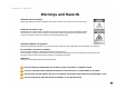
Warning: Exposure to Radio Frequency Radiation The radiated output power of this device is far below the FCC radio frequency exposure limits. Nevertheless, the device should be used in such a manner that the potential for human contact during normal operation is minimized. In order to avoid the possibility of exceeding the FCC radio frequency exposure limits, human proximity to the antenna should not be less than 40cm during normal operation. The gain of the antenna is 12 dBi.