
User's Manual
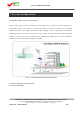
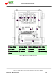
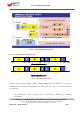
Table Of Contents

FCC ID : U88GSTR1937DT-SPR
HYUNDAI CALIBRATION & CERTIFICATION TECHNOLOGIES CO., LTD.
SAN 136-1, AMI-RI, BUBAL-EUP, ICHEON-SI, KYOUNGKI-DO, 467-701, KOREA
TEL:+82 31 639 8517 FAX:+82 31 639 8525 www.hct.co.kr
8
2.2.2 Uplink Path
FWD and RVS Gain Budgets have similar structure. In case of Uplink Path, RF signal is
transmitted from Service Antenna to Service Cavity Filter and RVS LNA division, then the signal
is transferred to IF division, where desirable Band is selected by passing 6 Paths of RF Switch
and SAW filter. Selected Band is got together in FWD LNA division, and then transmitted to
Donor Antenna passing through Digital ATT (10dB ATT Range) and Donor Cavity Filter. Then the
signal is transmitted to BTS through Donor Antenna.
<Pic.5> Uplink Block Diagram
2.2.3 Downlink Path
Downlink Path is organized in reverse order of Uplink Path.
In case of Downlink Path, RF signal is transmitted from Donor Antenna to Donor Cavity Filter
and FWD LNA division, then the signal is transferred to IF division, where desirable Band is
selected by passing 6 Paths of RF Switch and SAW filter. Attenuation range is 40dB in Digital
Attenuator. Selected Band is transmitted to FWD Drive Am and Service Cavity Filter, after that
the signal is transferred to Service Antenna.
Report No. : HCT-R07-014 8/24