STC 160 Head-End Station Quad modulators HMM 470 HMS 470 Notes on the Assembly Instructions As well as this supplementary Assembly Instructions, the Assembly Instructions for the STC 160 apply. English Assembly Instructions Grundig SAT SystEms GSS Grundig SAT Systems GmbH Beuthener Strasse 43 D-90471 Nuremberg Phone: Fax: Email: Internet: +49 (0) 911 / 703 8877 +49 (0) 911 / 703 9210 info@gss.tv www.gss.
Contents 1 Safety regulations................................................................................................ 3 2 General information............................................................................................. 3 2.1 Scope of delivery................................................................................... 3 2.2 Meaning of the symbols used................................................................... 3 2.3 Technical data.........................................
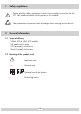
1 Safety regulations Please read the safety regulations listed in the assembly instructions for the STC 160 head-end station which pertain to this module. Take precautions to prevent static discharge when working on the device! 2 General information 2.1 Scope of delivery 1 HMM 470 or HMS 470 module 1 HF cable with F plugs 1 CD (assembly instructions) 1 Brief Assembly Instructions 2.
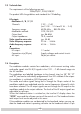
2.3 Technical data The requirements of the following are met: 2006/95/EC, 2004/108/EC The product fulfils the guidelines and standards for CE labelling. HF outputs: Modulators A / B / C / D Channels: Frequency range: Modulation method: Output level: Output impedance: Video signal-to-noise ratio: Video frequency response: Audio frequency response: C 02 … C 69 (incl. S 03 … S 14 and S 16 … S 41) 48.25 MHz … 855.25 MHz CCIR, PAL B/G typ. 86 dBµV 75 Ω, nominal typ.
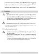
D-Sub socket, using a PC or notebook and the “BE-Flash” software. You can find the current operating software for the head-end station, the software “BE-Flash” and the current assembly instructions on the website “www.gss.tv”. The modules are designed exclusively for use in the STC 160 head-end station. 3 Installation Caution – Ensure the head end station is mounted so it will not be able to vibrate.
• Open the housing of the head-end station in accordance with the assembly instructions for the STC 160. • Open the locking device 1 in the direction of the arrow (fig. 1). Fig. 1 —> Slots 1 (digital module) and 2 (modulator module) are shown in figure 2. The open slot in between (without a contact strip on the board at the rear wall of the housing) is intended for an add-on module. • Insert the modulator module in grooves A and B (fig.
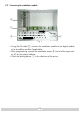
3.2 Connecting the modulator module ! " Fig. 3 • Using the AV cable C, connect the modulator module to the digital module or to an add-on module if applicable. • After programming, connect the modulator output D to one of the input sockets E on the output collector. • Close the locking device 1 in the direction of the arrow.
4 The control panel at a glance 4.1 Menu items Program the module using the buttons on the head-end station control unit. The menus appear on the two-line display of the control unit. You can use the M button to select the following menu items: – – – – – Modulator settings Modulator output channel Output level Audio setting Storing 4.
5 Programming 5.1 Preparation • Connect the test receiver to the HF output on the modulator module. • Adjust the test receiver to the output channel of the channel strip to be set. • Switch on the modulator if necessary. For each modulator, there is a green LED which indicates if the modulator is switched on. LED – Channel strip “A“ LED – Channel strip “B“ LED – Channel strip “C“ LED – Channel strip “D“ The process of programming the HMM 470 and HMS 470 modules is the same, with one exception.
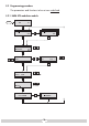
5.2 Programming procedure The parameters and functions to be set are underlined. 5.2.
5.2.
5.3 Programming the HMM 470 modulator module Notes: – Entries are saved by pressing the S button. —> You will be returned to the item “Selecting the module/channel strip”. – The programming process can be cancelled by pressing and holding the M button. —> You will be returned to the item “Selecting the module/channel strip”. Switch on the head-end station. —> The display shows “SETUP BE160” and the software version of the head-end station (e.g. V 7).
• Press the M button: W S B modulator” 4 A MON – MO —> The “Switching Bx onC5 the 1 S3 4 0 ,S “OUTPUT – Modulator” menu isC23 activated. Switching on the modulator Bx 2A / OUTPUT Modulator on on / off M Bx to 2 switch “on” the modulator •O Use the buttons / (LED 0 the modulator C 1 4 … 63 illuminates – page 9), or to switchi e“off” if Böx 4 necessary (LED is switched Bx 2B off). MONO 4 • Press the M button. M —> The “Setting the output channel” – “OUTPUT” menu is activated.
Setting the fine tuning Only change the fine tuning (frequency offset) in circumstances where it is absolutely necessary to do so. Once you have changed it, all televisions BconnectedT to the cable system will T Bx means 2B AV MONO AVfine MONO need to be calibrated by of tuning to match it. • Press the button. —> Pressing the button you can return to the “Setting the output channel” menu. • Use the buttons to adjust the fine tuning (Fine). / •OUPress the M button.
on signal of r O TPUT n audio Selecting the BIn … -15 d select between mono audio (Mono L) this menu, you can and the composite signal of the audio signals (Mono L + R). C212A Bx AUDIO / L / L+R Mono L M TP •O The buttons are usedC to select the audio signal EL (“Mono L” 0or “Mono 15 dB L + R”). • Press the M button. —> The “Storing data” – “MEMORY” menu is activated. Storing data Bx 2A MEMORY S => STORE M Bx 1A CANCEL S • All programmed data is saved by pressing the S button.
5.4 Programming the HMS 470 modulator module • Switch on the head-end station. —> The display shows “SETUP BE160” and the software version of the head-end station (e.g. V 7). Ein/On SETUP BE160 V7 5 SelectingC the module / channel C5 strip 2 S3- • Press repeatedly if necessary to select the particular 6 M “A”, “B”, “C” or “D” to be module (Bx …) or channel strip programmed. Bx 2A 4 AV STEREO Bx 2B 4 AV STEREO C21 C23 M M •OUTPU Press the M button to activate the channel strip.
Selecting the audio signal OUTPU In this menu, you/ can select between stereo and dual tone. If Bthe audio signal will be 0 … -15 B supplied by the digital module, it will be switched automatically. Bx 2A AUDIO / Stereo / Dual Stereo M • Using the button, select the desired audio signal E C NC L “Stereo” or “Dual”. • Press the M button. —> The “Storing data” – “MEMORY” menu is activated (page 15).
7 Channel and frequency tables C C C C C C 5 6 7 8 9 10 Bildträgerfrequenz Picture carrier frequency [MHz] 133.25 140.25 147.25 154.25 161.25 168.25 Kanal Channel 5 6 7 8 9 10 Kanal Channel Bildträgerfrequenz Picture carrier frequency [MHz] Kanal Channel S S S S S S Bildträgerfrequenz Picture carrier frequency [MHz] 48.25 55.25 62.25 112.25 119.25 126.