
Operation Manual


4. Installation
Do not install in a location subject to high temperature (over 50°C), low temperature (below -10°C), or high
humidity. Doing so may cause fire or electric shock. Keep out of direct sunlight and heat radiation sources. It may
cause fire. Avoid aiming the camera directly towards extremely bright objects such as sun, as this may damage
the CCD image sensor.
Do not install the unit in humid, dusty, or sooty locations. Doing so may cause fire or electric shock. Install it in a
place with good ventilation.
When installing the camera, fasten it securely and firmly. A falling camera may cause personal injury.
If you want to relocate the already installed product, be sure to turn off the power and then move or reinstall it.
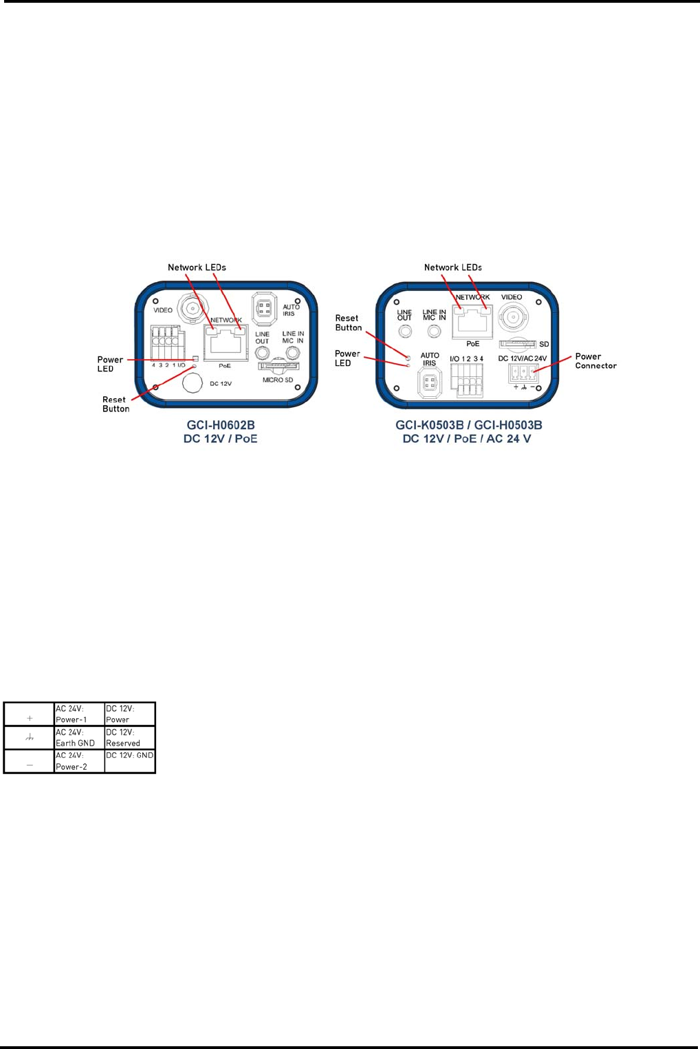
4.1. Camera Overview
1. LINE OUT & LINE IN / MIC IN: Two-way audio transmission
2. Power LED: Green light indicates good power connection.
3. Reset button: Press and hold the button for 5 seconds, and then the camera will reset to factory defaults.
After around 30 seconds, reconnect the camera by entering its default IP address: 192.168.1.1, in the URL bar.
4. AUTO IRIS connector: Auto iris lens connector
5. NETWORK (with PoE) Connector: RJ45 connector for LAN connection
6. Network LEDs: Green Link Light indicates good network connection. Orange Activity Light flashes for network
activity indication.
7. I/O Terminal Connector: For alarm connection
8. VIDEO (BNC connector): For video output
9. Micro SD Card slot: For video and snapshots storage
10. For GCI-H0602B: 12V connector / For GCI-K0503B and GCI-H0503B: AC 24V/DC 12V Connector (Please refer
to the table below for wiring of the AC 24V and DC 12V camera with the supplied power cable).
4.2. System Requirements
To perform the IP Camera via web browser, please ensure your PC is in good network connection, and meets the
system requirements as described below.
Personal Computer :
1.) Intel Pentium M, 2.16 GHz or Intel Core 2 Duo, 2.0 GHz
2.) 2 GB RAM or more
Operating System :
Windows VISTA or Windows XP
3
English