
Installation and Operating Instructions
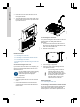
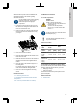
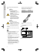
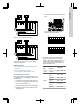
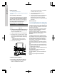
Table Of Contents
- English (GB)
- 1. General information
- 2. Installing the product
- 3. Starting up the product
- 4. Product introduction
- 5. Control functions
- 6. Setting the product
- 6.1 Setting the sensor type
- 6.2 Setting the start level
- 6.3 Setting the stop level
- 6.4 Setting the high level
- 6.5 Stop delay
- 6.6 Power-on delay
- 6.7 Dry-running protection
- 6.8 Using the same level switch for the start and stop level
- 6.9 "Multipump settings"
- 6.10 "Antiseizing"
- 6.11 Signal detection time
- 6.12 Setting the maximum number of restarts with Grundfos GO Remote
- 6.13 Setting the service interval with Grundfos GO Remote
- 6.14 Operating the product
- 6.15 Motor protection
- 6.16 Alarm reset
- 6.17 Setting the buzzer with Grundfos GO Remote
- 6.18 Setting units for Grundfos GO Remote
- 6.19 Setting units for the operating panel with Grundfos GO Remote
- 6.20 GENIbus
- 6.21 Security
- 6.22 Starting the startup wizard with the operating panel
- 7. Servicing the product
- 8. Fault finding the product
- 8.1 Overview of alarm and warning codes
- 8.2 Code 2 (Power phase missing)
- 8.3 Code 4 (Too many motor restarts)
- 8.4 Code 9 (Power phase sequence wrong)
- 8.5 Code 12 (Service needed)
- 8.6 Code 22 (Moisture in motor of pump)
- 8.7 Code 25 (Wrong configuration)
- 8.8 Code 26 (Contactor shorted)
- 8.9 Code 48 (Motor is overloaded)
- 8.10 Code 51 (Blocked)
- 8.11 Code 57 (Missing water in the application)
- 8.12 Code 69 (Winding temperature too high)
- 8.13 Code 72 (Internal fault)
- 8.14 Code 76 (Internal fault)
- 8.15 Code 84 (Memory storage media faulty)
- 8.16 Code 85 (Internal fault)
- 8.17 Code 117 (Door opened)
- 8.18 Code 159 (Communication error CIMxxx)
- 8.19 Code 163 (Drive unit configuration fault)
- 8.20 Code 165 (Signal fault)
- 8.21 Code 191 (High water level)
- 8.22 Code 205 (Level switch inconsistency)
- 8.23 Code 220 (Contactor wear out)
- 8.24 Code 229 (Water on floor)
- 9. Technical data
- 10. Disposing of the product

L2 L3L1
PE
N
NN
L2 L3
L1 N
EARTH
B
A
B
A
PE PTC1
PTC2
T2
T3T1
T2
T3
T1
M1
M2
TM070126
Three-phase connections for two pumps
L2 L3L1
PE
N
N
L2 L3
L1
EARTH
B
A
B
A
PE PTC1
PTC2
T2
T3T1
T2
T3
T1
M1
M2
TM072496
Three-phase connections for two pumps without
neutral, for Norway only
Related information
6.15.4 Setting the motor protection with Grundfos
GO Remote
8.2 Code 2 (Power phase missing)
8.4 Code 9 (Power phase sequence wrong)
2.3.4 Connecting a level sensor
You can either connect an analog level sensor, such
as a pressure sensor, or a digital level sensor, such
as a float switch.
1. Loosen the screws and remove the front cover.
Be careful not to damage the cable between the
front cover and the back cover.
2. Lead the wires through one of the cable glands.
3. Depending on the type of wire, take one of the
following actions:
• For a shielded wire, lead it through the cable
clamp.
CIO1
GND
TM070571
• For a not shielded wire, attach it to the
protection cover with a cable tie.
DIO1
GND DIO2
GND DI1 GND DI2
GND
CIO1
GND
CIO2 GND 24V
GND
24V GND
TM070760
4. Depending on the type and function of the
sensor, connect the wires to the following
terminals. When using an analog sensor, level
switches can be used to add redundance or
security by adding an extra dry-run sensor or
high-level sensor or both.
Sensor
type
Sensor
function
Terminals
Analog All levels
CIO1 - GND - 24
V
Digital
Dry-running
level
CIO2 - GND
Stop level DIO1 - GND
Start level,
pump 1
DIO2 - GND
Start level,
pump 2
DI1 - GND
High level DI2 - GND
9
English (GB)