
Installation and Operating Instructions
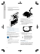
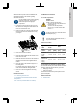
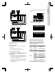
Table Of Contents
- English (GB)
- 1. General information
- 2. Installing the product
- 3. Starting up the product
- 4. Product introduction
- 5. Control functions
- 6. Setting the product
- 6.1 Setting the sensor type
- 6.2 Setting the start level
- 6.3 Setting the stop level
- 6.4 Setting the high level
- 6.5 Stop delay
- 6.6 Power-on delay
- 6.7 Dry-running protection
- 6.8 Using the same level switch for the start and stop level
- 6.9 "Multipump settings"
- 6.10 "Antiseizing"
- 6.11 Signal detection time
- 6.12 Setting the maximum number of restarts with Grundfos GO Remote
- 6.13 Setting the service interval with Grundfos GO Remote
- 6.14 Operating the product
- 6.15 Motor protection
- 6.16 Alarm reset
- 6.17 Setting the buzzer with Grundfos GO Remote
- 6.18 Setting units for Grundfos GO Remote
- 6.19 Setting units for the operating panel with Grundfos GO Remote
- 6.20 GENIbus
- 6.21 Security
- 6.22 Starting the startup wizard with the operating panel
- 7. Servicing the product
- 8. Fault finding the product
- 8.1 Overview of alarm and warning codes
- 8.2 Code 2 (Power phase missing)
- 8.3 Code 4 (Too many motor restarts)
- 8.4 Code 9 (Power phase sequence wrong)
- 8.5 Code 12 (Service needed)
- 8.6 Code 22 (Moisture in motor of pump)
- 8.7 Code 25 (Wrong configuration)
- 8.8 Code 26 (Contactor shorted)
- 8.9 Code 48 (Motor is overloaded)
- 8.10 Code 51 (Blocked)
- 8.11 Code 57 (Missing water in the application)
- 8.12 Code 69 (Winding temperature too high)
- 8.13 Code 72 (Internal fault)
- 8.14 Code 76 (Internal fault)
- 8.15 Code 84 (Memory storage media faulty)
- 8.16 Code 85 (Internal fault)
- 8.17 Code 117 (Door opened)
- 8.18 Code 159 (Communication error CIMxxx)
- 8.19 Code 163 (Drive unit configuration fault)
- 8.20 Code 165 (Signal fault)
- 8.21 Code 191 (High water level)
- 8.22 Code 205 (Level switch inconsistency)
- 8.23 Code 220 (Contactor wear out)
- 8.24 Code 229 (Water on floor)
- 9. Technical data
- 10. Disposing of the product

delivered with the product. See the installation and
operating instruction for the module regarding
electrical connections.
Use an antistatic service kit when handling
electronic components. This prevents
static electricity from damaging the
components.
1. Loosen the screws and remove the front cover.
Be careful not to damage the cable between the
front cover and the back cover.
2. Push the module on to the three guide pins and
into the socket. Press the module home, using
your fingers.
TM070130
3. Fit the screw to lock the module.
4. Place the labels supplied with the module on the
back of the front cover.
5. Make the electrical connections to the module as
described in the instructions supplied with the
module.
6. Route the wires for the module through one of
the cable glands.
For modules with LAN or antenna cables, you
must order an additional cable gland M20.
7. Fit the cover and cross-tighten the mounting
screws.
Related information
2.2.1 Removing the front cover
4.7 Supported communication interface modules
and protocols
8.18 Code 159 (Communication error CIMxxx)
2.3 Electrical connection
2.3.1 Cable requirements
DANGER
Electric shock
Death or serious personal injury
‐ The wires from the pump phases must
be rated at 90 °C.
‐ The wires from the temperature
sensor, if any, must be rated at 480 V
and 70 °C.
For the US market only, use flexible metal
conduits (FMC) only.
The wires from the temperature sensor, if
any, must be shielded.
Cable cross sections
Type of
cable
Stranded with
ferrule
Solid
Cross
section
[mm
2
]
[AWG]
[mm
2
]
[AWG]
Contactor
for the
pump
1.5 - 2.5 16-14 1.5 - 4 16-12
Terminal
block for the
power
supply
2.5 - 10 14-8 2.5 - 16 14-6
2.3.2 Protection of controller and supply cables
The controller and the power cables must be overload
protected. Protection must be done by a pre-fuse:
• Melt type gL and gG
• Auto fuse of type C
See the rated current of this specific product on the
product nameplate.
Related information
9. Technical data
7
English (GB)