
Installation and Operating Instructions
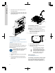
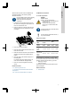
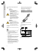
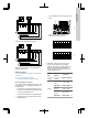
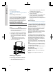
Table Of Contents
- English (GB)
- 1. General information
- 2. Installing the product
- 3. Starting up the product
- 4. Product introduction
- 5. Control functions
- 6. Setting the product
- 6.1 Setting the sensor type
- 6.2 Setting the start level
- 6.3 Setting the stop level
- 6.4 Setting the high level
- 6.5 Stop delay
- 6.6 Power-on delay
- 6.7 Dry-running protection
- 6.8 Using the same level switch for the start and stop level
- 6.9 "Multipump settings"
- 6.10 "Antiseizing"
- 6.11 Signal detection time
- 6.12 Setting the maximum number of restarts with Grundfos GO Remote
- 6.13 Setting the service interval with Grundfos GO Remote
- 6.14 Operating the product
- 6.15 Motor protection
- 6.16 Alarm reset
- 6.17 Setting the buzzer with Grundfos GO Remote
- 6.18 Setting units for Grundfos GO Remote
- 6.19 Setting units for the operating panel with Grundfos GO Remote
- 6.20 GENIbus
- 6.21 Security
- 6.22 Starting the startup wizard with the operating panel
- 7. Servicing the product
- 8. Fault finding the product
- 8.1 Overview of alarm and warning codes
- 8.2 Code 2 (Power phase missing)
- 8.3 Code 4 (Too many motor restarts)
- 8.4 Code 9 (Power phase sequence wrong)
- 8.5 Code 12 (Service needed)
- 8.6 Code 22 (Moisture in motor of pump)
- 8.7 Code 25 (Wrong configuration)
- 8.8 Code 26 (Contactor shorted)
- 8.9 Code 48 (Motor is overloaded)
- 8.10 Code 51 (Blocked)
- 8.11 Code 57 (Missing water in the application)
- 8.12 Code 69 (Winding temperature too high)
- 8.13 Code 72 (Internal fault)
- 8.14 Code 76 (Internal fault)
- 8.15 Code 84 (Memory storage media faulty)
- 8.16 Code 85 (Internal fault)
- 8.17 Code 117 (Door opened)
- 8.18 Code 159 (Communication error CIMxxx)
- 8.19 Code 163 (Drive unit configuration fault)
- 8.20 Code 165 (Signal fault)
- 8.21 Code 191 (High water level)
- 8.22 Code 205 (Level switch inconsistency)
- 8.23 Code 220 (Contactor wear out)
- 8.24 Code 229 (Water on floor)
- 9. Technical data
- 10. Disposing of the product

3. Place the front cover above the back cover on
the support brackets.
4. To ensure that the front cover does not tilt, insert
the two bottom screws into the open holes at the
top of the back cover.
TM071322
Related information
2.2.3 Installing the control unit
2.2.4 Installing a communication interface module
2.3.4 Connecting a level sensor
3.6 Configuring the IO terminals using Grundfos GO
Remote
2.2.2 Disconnecting the front cover
If you need to remove the front cover completely, you
must remove the flat cable between the front cover
and the back cover.
Use an antistatic service kit when handling
electronic components. This prevents
static electricity from damaging the
components.
1. Loosen the screws.
2. Carefully separate the front cover from the back
cover.
3. Pull out the flat cable that is connected to the
circuit board. Do not remove the flat cable from
the front cover.
TM071323
2.2.3 Installing the control unit
The product is designed to be mounted on a flat and
vertical surface. The cable glands must face
downwards.
1. Loosen the screws and remove the front cover.
Be careful not to damage the cable between the
front cover and the back cover.
2. Drill holes in the surface.
165 (6.5")
255 (10.0")
115 (4.5")
TM070121
3. Insert wall plugs, if applicable.
4. Fit the four screws in the mounting holes and
cross-tighten the screws.
The mounting screws must have a
minimum length of 32 mm (Ø 8.2
mm). If the wall is more than 3 mm
uneven, insert rubber blocks between
the surface and the control unit to
even the surface. The box of the
control unit must not be bent.
Related information
2.2.1 Removing the front cover
2.2.4 Installing a communication interface module
You can fit a communication interface module (CIM)
in the control unit to enable communication with
external systems. The module is optional and is not
6
English (GB)