
Installation and Operating Instructions
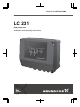
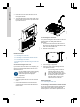
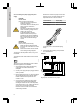
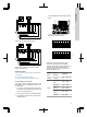
Table Of Contents
- English (GB)
- 1. General information
- 2. Installing the product
- 3. Starting up the product
- 4. Product introduction
- 5. Control functions
- 6. Setting the product
- 6.1 Setting the sensor type
- 6.2 Setting the start level
- 6.3 Setting the stop level
- 6.4 Setting the high level
- 6.5 Stop delay
- 6.6 Power-on delay
- 6.7 Dry-running protection
- 6.8 Using the same level switch for the start and stop level
- 6.9 "Multipump settings"
- 6.10 "Antiseizing"
- 6.11 Signal detection time
- 6.12 Setting the maximum number of restarts with Grundfos GO Remote
- 6.13 Setting the service interval with Grundfos GO Remote
- 6.14 Operating the product
- 6.15 Motor protection
- 6.16 Alarm reset
- 6.17 Setting the buzzer with Grundfos GO Remote
- 6.18 Setting units for Grundfos GO Remote
- 6.19 Setting units for the operating panel with Grundfos GO Remote
- 6.20 GENIbus
- 6.21 Security
- 6.22 Starting the startup wizard with the operating panel
- 7. Servicing the product
- 8. Fault finding the product
- 8.1 Overview of alarm and warning codes
- 8.2 Code 2 (Power phase missing)
- 8.3 Code 4 (Too many motor restarts)
- 8.4 Code 9 (Power phase sequence wrong)
- 8.5 Code 12 (Service needed)
- 8.6 Code 22 (Moisture in motor of pump)
- 8.7 Code 25 (Wrong configuration)
- 8.8 Code 26 (Contactor shorted)
- 8.9 Code 48 (Motor is overloaded)
- 8.10 Code 51 (Blocked)
- 8.11 Code 57 (Missing water in the application)
- 8.12 Code 69 (Winding temperature too high)
- 8.13 Code 72 (Internal fault)
- 8.14 Code 76 (Internal fault)
- 8.15 Code 84 (Memory storage media faulty)
- 8.16 Code 85 (Internal fault)
- 8.17 Code 117 (Door opened)
- 8.18 Code 159 (Communication error CIMxxx)
- 8.19 Code 163 (Drive unit configuration fault)
- 8.20 Code 165 (Signal fault)
- 8.21 Code 191 (High water level)
- 8.22 Code 205 (Level switch inconsistency)
- 8.23 Code 220 (Contactor wear out)
- 8.24 Code 229 (Water on floor)
- 9. Technical data
- 10. Disposing of the product

9. Technical data ................28
10. Disposing of the product ..........30
1. General information
Read this document before you install the
product. Installation and operation must
comply with local regulations and accepted
codes of good practice.
1.1 Hazard statements
The symbols and hazard statements below may
appear in Grundfos installation and operating
instructions, safety instructions and service
instructions.
DANGER
Indicates a hazardous situation which, if
not avoided, will result in death or serious
personal injury.
WARNING
Indicates a hazardous situation which, if
not avoided, could result in death or
serious personal injury.
CAUTION
Indicates a hazardous situation which, if
not avoided, could result in minor or
moderate personal injury.
The hazard statements are structured in the following
way:
SIGNAL WORD
Description of the hazard
Consequence of ignoring the warning
• Action to avoid the hazard.
1.2 Notes
The symbols and notes below may appear in
Grundfos installation and operating instructions,
safety instructions and service instructions.
Observe these instructions for explosion-
proof products.
A blue or grey circle with a white graphical
symbol indicates that an action must be
taken.
A red or grey circle with a diagonal bar,
possibly with a black graphical symbol,
indicates that an action must not be taken
or must be stopped.
If these instructions are not observed, it
may result in malfunction or damage to the
equipment.
Tips and advice that make the work easier.
2. Installing the product
2.1 Location
Install the product in a location that meets the
following requirements:
• Place the product in a flood-safe place.
• Make sure that the ambient temperature is within
the limits.
• Install the product as close as possible to the
connected pumps, sensors, and accessories.
• The product must be protected from direct
sunlight.
• The product must be easily accessible.
• Outdoor installation: the product must be
installed in a protective shed or enclosure, class
IP 54.
• Indoor installation:The product must be installed
in a well-ventilated room to ensure cooling of its
components.
2.2 Mechanical installation
2.2.1 Removing the front cover
The front cover must be removed to make any
connections or to install the Communication Interface
Module (CIM).
Use an antistatic service kit when handling
electronic components. This prevents
static electricity from damaging the
components.
Place the front cover above the control unit, if
possible. This way you do not need to remove the flat
cable between the front cover and the control unit.
1. Loosen the screws.
2. Carefully separate the front cover from the back
cover.
Be careful not to damage the cable connecting
the front cover and the back cover.
5
English (GB)