
Installation and Operating Instructions
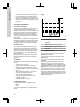
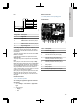
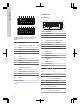
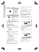
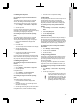
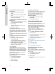
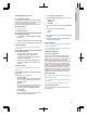
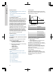
Table Of Contents
- English (GB)
- 1. General information
- 2. Installing the product
- 3. Starting up the product
- 4. Product introduction
- 5. Control functions
- 6. Setting the product
- 6.1 Setting the sensor type
- 6.2 Setting the start level
- 6.3 Setting the stop level
- 6.4 Setting the high level
- 6.5 Stop delay
- 6.6 Power-on delay
- 6.7 Dry-running protection
- 6.8 Using the same level switch for the start and stop level
- 6.9 "Multipump settings"
- 6.10 "Antiseizing"
- 6.11 Signal detection time
- 6.12 Setting the maximum number of restarts with Grundfos GO Remote
- 6.13 Setting the service interval with Grundfos GO Remote
- 6.14 Operating the product
- 6.15 Motor protection
- 6.16 Alarm reset
- 6.17 Setting the buzzer with Grundfos GO Remote
- 6.18 Setting units for Grundfos GO Remote
- 6.19 Setting units for the operating panel with Grundfos GO Remote
- 6.20 GENIbus
- 6.21 Security
- 6.22 Starting the startup wizard with the operating panel
- 7. Servicing the product
- 8. Fault finding the product
- 8.1 Overview of alarm and warning codes
- 8.2 Code 2 (Power phase missing)
- 8.3 Code 4 (Too many motor restarts)
- 8.4 Code 9 (Power phase sequence wrong)
- 8.5 Code 12 (Service needed)
- 8.6 Code 22 (Moisture in motor of pump)
- 8.7 Code 25 (Wrong configuration)
- 8.8 Code 26 (Contactor shorted)
- 8.9 Code 48 (Motor is overloaded)
- 8.10 Code 51 (Blocked)
- 8.11 Code 57 (Missing water in the application)
- 8.12 Code 69 (Winding temperature too high)
- 8.13 Code 72 (Internal fault)
- 8.14 Code 76 (Internal fault)
- 8.15 Code 84 (Memory storage media faulty)
- 8.16 Code 85 (Internal fault)
- 8.17 Code 117 (Door opened)
- 8.18 Code 159 (Communication error CIMxxx)
- 8.19 Code 163 (Drive unit configuration fault)
- 8.20 Code 165 (Signal fault)
- 8.21 Code 191 (High water level)
- 8.22 Code 205 (Level switch inconsistency)
- 8.23 Code 220 (Contactor wear out)
- 8.24 Code 229 (Water on floor)
- 9. Technical data
- 10. Disposing of the product

DIO1
GND DIO2 GND
DI1
GND
DI2 GND
CIO1
GND
CIO2 GND
24V GND 24V
GND
1 2
3
4
5
6 7
8
9 10 11 12 13 14 15 16
TM070124
Connect to Grundfos GO Remote to see which
options are available for the input and output
terminals.
Pos. Description
1 Digital input/output 1, configurable
2 GND
3 Digital input/output 2, configurable
4 GND
5 Digital input 1
6 GND
7 Digital input 2
8 GND
9 Configurable input/output 1,
10 GND
11 Configurable input/output 2
12 GND
13 Supply voltage, 24 V, max. 250 mA
14 GND
15 Supply voltage, 24 V, max. 250 mA
16 GND
Related information
3.6 Configuring the IO terminals using Grundfos GO
Remote
4.6 Identification
4.6.1 Nameplate
Type
P. N.
Made in Denmark
U
N
P.C.
S.N.
P1
V
hp 1PH
hp 3PH
DK - 8850 Bjerringbro Denmark
IP
Tamb
99350749
ENV
°C
1 2 3 4 5
6
7
8
9
14
13
12
10
11
115
200 230
460
TM072267
Pos. Description
1 Product name
2 Model
3 Maximum motor power, hp
4 Version number and material number
5 Production code, year and week
6 Serial number
7 Enclosure class according to IEC
8 Enclosure class according to NEMA
9 Factory code
10 Production site
11 Markings and approvals
12
Minimum to maximum ambient
temperature
13 Maximum current
14 Supply voltage
4.6.2 Type key
Example
LC 231 2x 1 - 7.5 DOL PI
Pos. 1 2 3 4 5
Pos. Description
1
Type:
• LC 231: wall-mounted version
2 Number of pumps supported
3 Current range of pump [A]
4
Starting method:
• DOL: direct-on-line
5
Panel type:
• PI: Plastic, for indoor use
14
English (GB)