
Installation and Operating Instructions
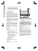
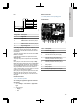
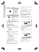
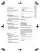
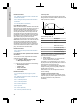
Table Of Contents
- English (GB)
- 1. General information
- 2. Installing the product
- 3. Starting up the product
- 4. Product introduction
- 5. Control functions
- 6. Setting the product
- 6.1 Setting the sensor type
- 6.2 Setting the start level
- 6.3 Setting the stop level
- 6.4 Setting the high level
- 6.5 Stop delay
- 6.6 Power-on delay
- 6.7 Dry-running protection
- 6.8 Using the same level switch for the start and stop level
- 6.9 "Multipump settings"
- 6.10 "Antiseizing"
- 6.11 Signal detection time
- 6.12 Setting the maximum number of restarts with Grundfos GO Remote
- 6.13 Setting the service interval with Grundfos GO Remote
- 6.14 Operating the product
- 6.15 Motor protection
- 6.16 Alarm reset
- 6.17 Setting the buzzer with Grundfos GO Remote
- 6.18 Setting units for Grundfos GO Remote
- 6.19 Setting units for the operating panel with Grundfos GO Remote
- 6.20 GENIbus
- 6.21 Security
- 6.22 Starting the startup wizard with the operating panel
- 7. Servicing the product
- 8. Fault finding the product
- 8.1 Overview of alarm and warning codes
- 8.2 Code 2 (Power phase missing)
- 8.3 Code 4 (Too many motor restarts)
- 8.4 Code 9 (Power phase sequence wrong)
- 8.5 Code 12 (Service needed)
- 8.6 Code 22 (Moisture in motor of pump)
- 8.7 Code 25 (Wrong configuration)
- 8.8 Code 26 (Contactor shorted)
- 8.9 Code 48 (Motor is overloaded)
- 8.10 Code 51 (Blocked)
- 8.11 Code 57 (Missing water in the application)
- 8.12 Code 69 (Winding temperature too high)
- 8.13 Code 72 (Internal fault)
- 8.14 Code 76 (Internal fault)
- 8.15 Code 84 (Memory storage media faulty)
- 8.16 Code 85 (Internal fault)
- 8.17 Code 117 (Door opened)
- 8.18 Code 159 (Communication error CIMxxx)
- 8.19 Code 163 (Drive unit configuration fault)
- 8.20 Code 165 (Signal fault)
- 8.21 Code 191 (High water level)
- 8.22 Code 205 (Level switch inconsistency)
- 8.23 Code 220 (Contactor wear out)
- 8.24 Code 229 (Water on floor)
- 9. Technical data
- 10. Disposing of the product

defined level is reached. If the pump is placed in
a well, this test may not be possible since the
pump cannot empty the well. Alternatively, pull
the dry-run level switch up to simulate a dry-run
situation. The same can be done with a pressure
level sensor.
4. Product introduction
4.1 Product description
The level-control unit switches the pump on and off
according to the liquid level measured by float
switches or a pressure sensor. When the start level is
reached, the pump starts, and when the liquid level
has been lowered to the stop level, the pump is
stopped by the control unit. An alarm is indicated in
case of for example high-water level in the tank or
sensor failure.
Basic settings are configured via the operating panel
and advanced settings are configured with Grundfos
GO Remote. Furthermore, you can read important
operating parameters with Grundfos GO Remote.
4.2 Intended use
The control unit is designed to control two pumps.
The product can be configured for two purposes:
emptying a wastewater pit or filling a pit or tank.The
product can be used for network pumping stations,
main pumping stations, commercial buildings and
municipal systems.
If the product is used in an explosive environment,
follow local regulations. If required use additional
equipment.
4.3 Features
The control unit features among others the following
functions:
• support of up to two pumps
• manual and automatic control of the pump
• Bluetooth pairing with Grundfos GO Remote
• operating indication, such as power on and pump
running
• alarm and warning indication, such as power
phase missing and high-water level
• motor and phase failure protection
• setting of stop delays matching the actual
operating conditions.
• automatic alternation of pumps.
4.4 Application types
You can choose between two application types:
• Empty
• Fill
You can set the application type with Grundfos GO
Remote.
Empty
1
2
3
4
5
TM0713341
Pos. Description
1 High level
2 Start level P2: start level for pump 2
3 Start level P1: start level for pump 1
4 Stop level
5 Dry-running level
The pump will start to empty the tank or pit when
Start level P1 is reached.
A second pump will start if the liquid level reaches
Start level P2.
The pump stops when the liquid level is lowered to
Stop level.
If the inflow of liquid exceeds the capacity of the
installed pump, the level in the tank or pit will rise.
Eventually, the High level sensor will register a high
liquid level in the tank or pit. If set, the signal from the
High level sensor can be used to activate an output
relay which can then be used to indicate a visual or
acoustic alarm or send a signal to a SCADA system.
If the pump is running and the liquid level in the tank
or pit falls below the dry-running level, the dry-running
protection will stop the pump to ensure that it is not
damaged mechanically.
12
English (GB)