
Installation Guide

6
6.1 Suction lift
The maximum suction lift of the pump can be
determined from the diagram, page 49.
Example:
If the suction lift is 10 ft, the length of the suction pipe
must not exceed 72 ft.
7. Mechanical installation
7.1 Location
The pump is suitable for indoor and outdoor
installation. It is resistant to sunlight.
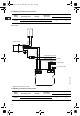
7.2 Foundation
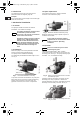
Mount the pump on the base plate with horizontal
suction port and vertical discharge port.
The pump must be installed horizontally.
The maximum permissible inclination angle is ± 18 °.
See fig. 2.
Fig. 2 Horizontal installation of the MQ
To prevent movement and vibrations, the pump and
base plate can be secured to a solid foundation by
means of the bolt holes in the base plate. For
pipework connection, see section 7.4 Pipework.
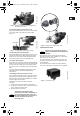
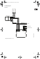
7.3 Space requirement
For inspection and service, allow a minimum
clearance of 60" behind the pump.
Fig. 3 Minimum clearance behind the pump
Being self-cooling, the pump requires no space or
ventilation at the sides.
7.4 Pipework
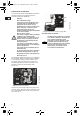
The pump is supplied with 1" NPT screwed
connections. Fit the connections in the suction and
discharge ports. See fig. 4. The pump discharge port
is flexible, ± 5 °, to facilitate the fitting.
Fig. 4 Fitting of screwed connections in suction
and discharge ports
Carefully screw the discharge connection into the
discharge port, using a spanner or similar tool.
Hold the discharge connection, and tighten the pump
discharge union nut with your hand. See fig. 5.
Fig. 5 Correct: Tighten the discharge union nut
with your hand
Note
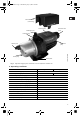
For outdoor installation, the pump must
be fitted with a protective cover
(accessory). See section 7.5 Protective
cover and 13. Accessories.
Note
Should the unlikely event of an internal
leakage occur, pumped liquid will be
drained out from the base and/or end
cover instead of damaging the pump.
Install the pump in such a way that no
undesirable collateral damage can
arise.
TM01 9691 2600
Max. ± 18 °
TM04 3746 5008
Note
Ensure that the maximum ambient
temperatures do not exceed the values
stated in section 6. Operating
conditions.
Note
Never use unnecessary force when
connecting the pipes.
TM01 9698 2600TM04 4271 1009
60"
Grundfos.bk Page 6 Wednesday, July 1, 2009 3:20 PM