
Installation Guide

4
CONTENTS
Page
1. Introduction 4
2. Items supplied 4
3. Symbols used in this document 4
4. Applications 4
4.1 Pumped liquids 4
5. Identification 4
5.1 Type key 4
6. Operating conditions 5
6.1 Suction lift 6
7. Mechanical installation 6
7.1 Location 6
7.2 Foundation 6
7.3 Space requirement 6
7.4 Pipework 6
7.5 Protective cover 7
8. Electrical connection 8
8.1 Generator or inverter 8
8.2 Wiring diagram 9
8.3 Winding resistance measurement 10
8.4 Winding resistance measurement 10
8.5 Start-up 11
9. Functions 11
9.1 Control panel 11
9.2 Pump stop 13
10. Maintenance 13
10.1 Service kits 13
10.2 Start-up after a long period of inactivity 13
11. Service 13
12. Technical data 14
12.1 Dimensions 14
12.2 Electrical data 14
12.3 Approvals 14
13. Accessories 14
14. Fault finding chart 15
15. MQ frequently asked questions 16
16. Disposal 16
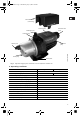
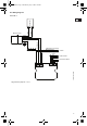
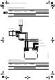
1. Introduction
The MQ is a low-noise water supply system
consisting of pump, motor, pressure tank and
controller combined into one compact unit. The
system is suitable for both indoor and outdoor use.
The self-priming pump starts automatically when
water is consumed in the installation and stops when
consumption ceases. The internal, built-in non-return
valve prevents backflow during priming and
operation.
The MQ pump incorporates overtemperature and
dry-running protection as well as a user-friendly
control panel.
The built-in pressure tank reduces the number of
starts and stops in case of leakage in the installation.
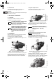
2. Items supplied
The MQ packaging contains these items:
• MQ water supply system with built-in non-return
valve
• non-return inlet valve in plastic bag
• installation and operating instructions.
3. Symbols used in this document
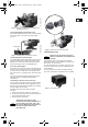
4. Applications
The MQ water supply system is designed for these
typical applications:
• water pressure boosting
(maximum inlet pressure: 40 psi)
• water supply from wells (maximum suction lift:
25 ft), for example
- in private homes
- on farms
- in market gardens and other large gardens.
The pump is suitable for rain water.
4.1 Pumped liquids
Thin, clean, non-aggressive liquids, not containing
solid particles or fibres.
5. Identification
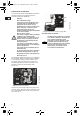
5.1 Type key
Warning
Prior to installation, read these
installation and operating instructions.
Installation and operation must comply
with local regulations and accepted
codes of good practice.
Warning
If these safety instructions are not
observed, it may result in personal
injury!
Caution
If these safety instructions are not
observed, it may result in malfunction
or damage to the equipment!
Note
Notes or instructions that make the job
easier and ensure safe operation.
Example MQ 3 -35 A -O -A BVBP
Pump type
Nominal flow rate [m³/h]
Head [m]
Code for pump version
A: Standard
Code for pipework connection
Code for materials
A: Standard
Code for shaft seal
Grundfos.bk Page 4 Wednesday, July 1, 2009 3:20 PM