
Installation Guide

Starting the Pump
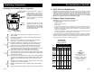
3a. Speed Selection
(three speed, all models except 3 x 460V & 575V)
The speed switch in the terminal box can be turned to three positions. The speed in the
three positions appears in the table below (also see Fig.13).
Speed in % of
Switch Maximum Speed
Position Single-Phase Three-Phase
Pumps Pumps
1 approx. 60% approx. 70%
2 approx. 80% approx. 85%
3 100% 100%
Changing to lower speeds offers considerable reduction in energy consumption and less
noise in the system.
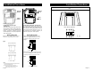
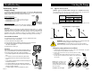
Pump Performance at Speed Settings
H
Q
12
Q
H
H
Q
3
Fig.13 H=Head and Q=Flow)
WARNING: Never make any connections in the pump terminal box
unless the electricity supply has been switched off.
AVERTISSEMENT: Ne jamais établir de connexions dans la boîte de
jonction de la pompe à moins que l’alimentation électrique n’ait été coupée.
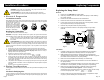
Change the pump performance as follows:
1. Switch off the electrical supply to the pump at the main circuit breaker. The green
indicator light in the terminal box must be off.
2. Remove the terminal box cover by loosening the four screws
in the cover.
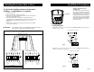
3. Pull out the speed switch module and re-insert it so that the
desired speed is visible through the window in the terminal box
(see Fig.14)
NOTE: When changing to and
from speed 1, the cover of the
speed switch module must be
removed and fitted on the other
side of the switch.
Continued on next page Fig.14
SPEEDSPEEDSPEED
Troubleshooting
Preliminary Checks
Supply Voltage
To check the voltage being supplied to the motor, use a voltmeter. Be careful, since
power is still being supplied to the pump. Do not touch the voltmeter leads
together while they are in contact with the power lines.
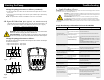
Three Phase Motors
Touch a voltmeter lead to:
• Power leads L1 and L2
• Power leads L2 and L3
• Power leads L3 and L1
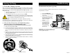
Single Phase Motors
Touch one voltmeter lead to each of the lines supplying
power to the pump L1 and L2 , (or L1 and N for 115V circuits).
Evaluation
When the motor is under load, the voltage should be within 10% (+ or -) of the
nameplate voltage. Any variation larger than this may indicate a poor electrical
supply and can cause damage to the motor windings. The motor should not be
operated under these conditions. Contact your power supplier to correct the
problem or change the motor to one requiring the voltage you are receiving.
Current Measurement
To check the current, use an ammeter. To do so, follow these steps:
1. Make sure the pump is operating
2. Set the ammeter to the proper scale.
3. Place the tongs of the ammeter around the leg to be measured.
4. Compare the results with the amp draw information on
the motor nameplate.
5. Repeat for the other legs.
Evaluation
If the current draw exceeds the listed nameplate amps, or
if the current imbalance is greater than 5% between each
leg on three phase units, then check the following:
• The voltage supplied to the pump maybe too high or too
low.
• The contacts on the motor starter may be burned.
• The terminals in the starter or terminal box may be
loose.
• There may be a winding defect. Check the winding and
insulation resistance
• The motor windings may be shorted or grounded.
• The pump may be damaged in some way and may be
causing a motor overload.
• A voltage supply or balance problem may exist.
}
These tests should give a
reading of full line voltage.
Checking
Single Phase
Power
L
1
L
2
Page 8
Page 11
Fig.19
Fig.18