
Installation Guide

Starting the Pump
1. Vent the Piping System
After the pump has been installed and the electrical connections made, the piping
system must be vented. Never operate the pump dry -- the system must first be filled
with liquid and vented. Do not vent the piping system through the pump. Instead,
follow these steps:
a. Fill and pressurize the system with liquid, and vent all trapped air from the
piping by suitable means.
b. If any isolation valves are used, make sure they are OPEN.
WARNING: If the vent screw is to be loosened, care should be taken
to ensure that the escaping scalding hot liquid does not cause personal
injury or damage to components (see Fig. 12).
AVERTISSEMENT: S’il faut desserrer la vis de purge, prendre les mesures
nécessaires pour que le liquide brûlant qui s’échappe ne cause pas de blessures
ou de dommages aux composants (voir la figure 12).
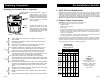
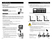
2. Check the Direction of Shaft Rotation
APPLIES TO 460V & 575V 2-SPEED MODELS ONLY
(three speed pumps direction of rotation is checked by fault finding chart, page 10)
a. Make sure that the power is OFF.
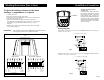
b. Unscrew and remove the vent plug located at the center of the nameplate.
c. Insert a small, flat-blade screwdriver into the slot in the end of the motor shaft
(see Fig.12). Rotate the shaft with the screwdriver to make sure it does so
freely.
d. Briefly start and stop the pump and watch to see which direction the shaft
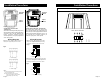
rotates. The shaft must rotate in the counterclockwise direction as shown on
the nameplate (see Fig.11).
e. If the pump shaft is rotating incorrectly, disconnect the power and interchange
any two power leads in the terminal box.
f. Check once again for proper counterclockwise rotation. When it is rotating
correctly, replace the vent plug.
Direction of Rotation
Vent Plug
Fig.11
Fig.12
Page 12
Page 7
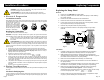
Troubleshooting
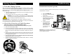
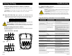
Insulation Resistance (lead-to-ground)
To check the insulation resistance (lead-to-ground) of the motor and leads, a
megohmmeter is required.
1. Turn the POWER OFF.
2. Disconnect all electrical leads
to the motor.
3. Set the scale selector on the
megohmmeter to R x 100K,
touch its leads together, and
adjust the indicator
to zero.
4. Touch the leads of
the megohmmeter
individually to each
of the motor leads
and to ground (i.e.
L1 to ground; L2 to
ground, etc.).
Evaluation: The resistance values for new
motors must exceed 1,000,000 ohms. If they
do not, replace the motor.
Fig.20