
Installation Guide

Page 13
Installation Procedures
L1
L2
L3
P1
P2
T6
T4
T5
T1
T2
T3
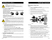
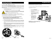
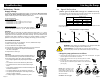
VersaFlo UPS 3x460V & 575V
Terminal Box:
All VersaFlo UPS single head pumps
with 3 phase x 460V & 575V terminal
boxes (Fig.8) come with a special two
speed terminal box. The speed is
changed by the orientation of the jumpers
as shown on page 9. All are equipped
with an internal thermal overload switch
(terminals P1 & P2) to be connected to
external contactor.
L3
L1
L2
K
K
L3
L2
L1
Start
K
Stop
P1
P2
T3 T2
T1
K
K
L3
L2
L1
Start/stop
L3
L1
L2
P1
P2
T3 T2 T1
Jumpers
3~ x 460 & 575 volt supply
3~ x 460 & 575 volt supply
Fig.9 shows the electrical connections when using external impulse contacts (momentary contacts) for
start/stop push button station.
Fig.10 shows the electrical connections when using an external changeover contact (maintained
contacts) for start/stop push button station.
Fig.8
Page 6
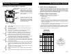
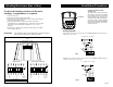
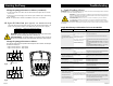
Winding Resistance (line to line)
To check the winding resistance of the motor
windings, a megohmmeter is required.
1. Turn the power off
2. Disconnect all electrical leads to the motor.
3. Set the scale on the megohmmeter to Rx1, touch its leads together
and adjust the indicator to zero.
4. Using the charts below for reference, touch the leads of the
megohmmeter to the appropriate pair of connectors. Check all pairs
that are present and write down and label (R
A
, R
SI
, R
S2
, R) all
readings.
5. Compare your readings to the matching model, phase and voltage
on the chart on page 15.
Evaluation : The resistance values must fall within the tolerances listed on
the next page. If they do not, replace the motor.
Wiring Diagrams
Fig.9
Fig.10
Internal Wiring
UPS
Terminal plug in stator
Single Phase
Three Phase 208-230V
R
A
: 6-1 or 6-1, 7-2
R
S1
: 12-8 or 12-8, 14-9
R
S2
: 4-10 or 4-10, 5-11
R: 5-9 or 5-9, 7-14
R: 11-12 or 11-12, 1-10
R: 4-6 or 4-6, 8-2
A: Main winding
S
2
: Auxiliary winding
S
1
: Auxiliary winding