
Installation Guide

Page 14
Installation Procedures
K
K
K
Stop
Start
L1L2L3T2T1
L1L2L3
K
K
Start/Stop
L1L2L3T2T1
L1L2L3
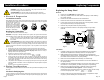
Wiring Diagrams
Fig.4
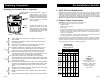
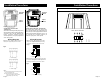
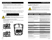
VersFlo UPS 3x208-230V Terminal Box:
All VersaFlo UPS single head pumps come
with a standard module and a speed switch as
shown in Fig.5. All are equipped with an internal
thermal overload switch (terminals T1 & T2, to
be connceted to an external contactor) to
protect the pump at all three speeds.
Page 5
Speed
Switch
Standard
Module
Fig.5
Protection
Module
Speed
Switch
VersFlo UPS 1x115V & 230V
Terminal Box:
All VersaFlo UPS single head pumps come
with a protection module and a speed switch
as shown in Fig.3. All are equipped with
built-in, automatic resetting, thermal
overload protection. The pump is protected
at all three speeds.
Fig.3
Wiring Diagrams
Fig.6
Fig.7
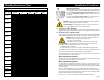
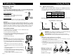
Fig.4 shows the electrical connections for a
single phase pump with protection module.
Fig.6 shows the electrical connections when
using external impulse contacts (momentary
contacts)for start/stop push button station.
Fig.7 shows the electrical connections when using
an external changeover contact (maintained
contacts) for start/stop push button station.
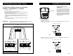
1~ x115V supply
Notes:
Provide electrical disconnect and current protection
as per local electrical codes.
K = External contactor sized to FL & LR
pump current. Auxilary contacts rated for
supply voltage (figure 6 & 9 only).
3~ x208-230 volt supply
3~ x208-230 volt supply
1~ x230V supply
L1 L2
Internal Wiring
UPS
Terminal plug in stator
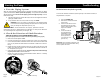
Three Phase 460/575V
R: 1-7
R: 3-9
R: 5-11
1
7
3
9
5
11
13
15
Installation Procedures