
Installation Guide

Page 15
Installation Procedures
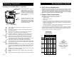
Mounting Positions
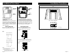
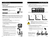
The arrows on the flanges of the pump indicate the direction of water flow.
Although the VersaFlo UPS may be installed in either vertical or horizontal
piping, the motor shaft must always remain horizontal, as shown in
Fig. 1 of the Terminal Box Position instructions and as shown in Fig.
2 to the left.
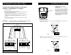
Also remember: Pumps installed outdoors must be protected by a
ventilated, watertight cover to keep out moisture and dirt.
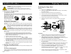
3. Connect the Pump
Install the pump into the piping system. Grundfos recommends that pressure gauges be
installed in the inlet and discharge flanges or pipes to check pump and system performance.
WARNING: The pump must be positioned so that someone cannot accidentally
come into contact with the hot surfaces of the pump.
AVERTISSEMENT: La pompe doit être placée de sorte que personne ne
puisse accidentellement toucher ses surfaces chaudes.
4. Electrical Connection
The electrical connection and protection should be carried out in accordance with the latest
edition of the National Electrical Code, local codes and regulations by a qualified electrician.
WARNING: Never make any connections in the pump terminal box
unless the electrical supply has been switched off.
• The pump must be grounded.
• The pump must be connected to an external main power switch.
AVERTISSEMENT: Ne jamais établir de connexions dans la boîte de jonction de
la pompe à moins que l’alimentation électrique n’ait été coupée.
• La pompe doit être mise à la terre.
• La pompe doit être raccordée à un interrupteur d’alimentation principale externe.
The operating voltage and frequency are marked on the pump nameplate. Make sure
that the motor is suitable for the electrical supply it is being installed to.
The pump should be grounded to protect against indirect contact and a ground fault
interrupter can be used as extra protection.
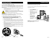
Multi-Speed Pump (1 phase)
All single phase pumps are equipped with built-in, automatic resetting, thermal overload
protection. The pump is protected at all three speeds.
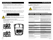
Multi-Speed Pump (3 phase)
The pump must be connected to the electrical supply via an external contactor. The
contactor must be connected to the built in thermal overload switch terminals T1 and
T2 (3x208-230V) or P1 and P2 (3x460V & 575V) to protect the pump against overloading
at all three speeds.
OR: If the pump is protected by means of a motor starter, the starter must be set
to the current consumption of the pump at the selected speed. The motor starter setting
must be changed every time the pump speed is changed. The current consumption at the
individual speeds is stated on the pump nameplate.
Figures 4, 6, 7, 9, and 10 on the next page show the possible connections:
Fig.2
Page 4
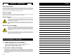
Winding Resistance Chart
60 HZ USA
UPS
Pump Type Voltage R RA RS1 RS2
1 x 115 V 17.8 - 23.2 3.95 - 5.20 9.40 - 12.4
1 x 230 V 70.0 - 91.5 17.0 - 22.2 39.5 - 52.0
UPS 32-40/4 3 x 208 - 230 V 180 - 236
3 x 460 V 360 - 470
3 x 575 V 575 - 750
1 x 115 V 9.55 - 12.6 3.05 - 4.00 6.70 - 8.80
1 x 230 V 19.4 - 25.5 5.45 - 7.10 12.6 - 16.4
UPS 32-80/2 3 x 208 - 230 V 44.0 - 57.5
3 x 460 V 83.5 - 110
3 x 575 V 132 - 174
1 x 115 V 4.15 - 5.45 1.20 - 1.56 2.65 - 3.50
1 x 230 V 8.30 - 10.8 2.20 - 2.90 5.05 - 6.65
UPS 32-160/2 3 x 208 - 230 V 26.0 - 34.0
3 x 460 V 53.5 - 70.0
3 x 575 V 84.5 - 110
1 x 115 V 11.4 - 15.0 2.95 - 3.85 5.60 - 7.35
1 x 230 V 50.5 - 66.5 14.0 - 18.4 25.5 - 34.0
UPS 40-40/4 3 x 208 - 230 V 118 - 154
3 x 460 V 234 - 310
3 x 575 V 360 - 475
1 x 115 V 5.60 - 7.35 1.84 - 2.42 4.50 - 5.90
1 x 230 V 11.0 - 14.4 3.95 - 5.20 8.55 - 11.2
UPS 40-80/2 3 x 208 - 230 V 32.0 - 42.0
3 x 460 V 64.0 - 84.0
3 x 575 V 102 - 132
1 x 115 V 4.15 - 5.45 1.94 - 2.55 3.30 - 4.35
1 x 230 V 8.10 - 10.6 3.05 - 4.00 4.60 - 6.05
UPS 40-80/4 3 x 208 - 230 V 46.5 - 61.0
3 x 460 V 90.5 - 118
3 x 575 V 164 - 216
1 x 115 V 2.85 - 3.75 1.10 - 1.44 1.94 - 2.55
1 x 230 V 5.60 - 7.35 2.02 - 2.66 3.75 - 4.95
UPS 40-160/2 3 x 208 - 230 V 22.8 - 30.0
3 x 460 V 45.5 - 59.5
3 x 575 V 72.0 - 95.0
1 x 230 V 6.80 - 8.95 2.02 - 2.65 3.70 - 4.85
UPS 40-240/2 3 x 208 - 230 V 11.0 - 14.4
3 x 460 V 22.0 - 29.0
3 x 575 V 35.0 - 45.5
1 x 115 V 6.55 - 8.55 2.12 - 2.80 4.30 - 5.65
1 x 230 V 25.0 - 33.0 8.30 - 10.8 15.0 - 19.8
UPS 50-40/4 3 x 208 - 230 V 57.5 - 75.0
3 x 460 V 114 - 148
3 x 575 V 184 - 242
1 x 115 V 4.15 - 5.45 1.20 - 1.56 2.65 - 3.50
1 x 230 V 8.30 - 10.80 2.20 - 2.90 5.05 - 6.65
UPS 50-80/2 3 x 208 - 230 V 26.0 - 34.0
3 x 460 V 33.5 - 70.0
3 x 575 V 84.5 - 110
1 x 115 V 2.75 - 3.60 1.74 - 2.30 2.85 - 3.75
1 x 230 V 5.50 - 7.25 2.65 - 3.50 4.95 - 6.50
UPS 50-80/4 3 x 208 - 230 V 37.0 - 49.0
3 x 460 V 79.0 - 104
3 x 575 V 120 - 156
1 x 230 V 6.80 - 8.95 2.02 - 2.65 3.70 - 4.85
UPS 50-160/2 3 x 208 - 230 V 12.4 - 16.2
3 x 460 V 24.2 - 31.5
3 x 575 V 37.5 - 49.5
3 x 208 - 230 V 7.80 - 10.2
UPS 50-240/2 3 x 460 V 15.6 - 20.6
3 x 575 V 25.0 - 33.0
3 x 208 - 230 V 46.5 - 61.0
UPS 80-40/4 3 x 460 V 90.5 - 118
3 x 575 V 164 - 216
UPS 80-80/4 3 x 208 - 230 V 23.6 - 31.0
3 x 208 - 230 V 7.80 - 10.2
UPS 80 -160/2 3 x 460 V 15.6 - 20.6
3 x 575 V 25.0 - 33.0
3 x 208 - 230 V 27.5 - 36.0
UPS 100-40/4 3 x 460 V 54.5 - 71.5
3 x 575 V 86.0 - 114
[
ΩΩ
ΩΩ
Ω] 20°C - 50°C