
Installation Guide

Installation Procedures
1. Electrical Preparation
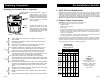
Terminal Box Position
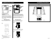
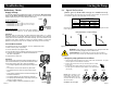
At the bottom of the stator, closest to the pump housing, there are two drain holes to allow
condensed water to escape. The drain holes must point downwards. As they are opposite
the terminal box position, the
terminal box must point
upwards in one of the positions
shown in Fig.1. The following
terminal box positions apply
whether the piping is mounted
vertically or horizontally.
Rotating the Terminal Box
To rotate the terminal box, follow these steps:
WARNING: If the pump is already installed in the system, the system must be drained
or the isolating valves on both sides of the pump must be closed before the allen head
screws are removed as the pumped liquid may be scalding hot and/or under
pressure. Do not start the pump until the system has been filled with liquid
and vented.
AVERTISSEMENT: Si la pompe est déjà installée, il faut drainer le système ou
fermer les deux robinets d’isolement latéraux de la pompe avant d’enlever les
vis à tête hexagonale, car le liquide pompé pourrait être brûlant et/ou sous
pression. Ne pas faire fonctionner la pompe jusqu’à ce que le système ait été rempli de
liquide et purgé.
1. Remove the four allen screws holding the pump head onto the pump housing
2. Carefully lift the pump head and rotate it so the terminal box is in the desired position.
DO NOT locate the terminal box beneath the pump. Make sure the O-ring is
properly seated in the pump housing.
3. Replace the pump head onto the pump housing
4. Tighten the allen head screws evenly. Torque to: 8mm ....... 15 ft lbs
10mm.....25 ft lbs
5. Check to make sure the rotor turns freely. Do this by removing the the vent plug in
the middle of the pump nameplate. Insert a medium size flat-blade screwdriver into
the slot at the exposed end of the shaft. Gently turn the shaft. If it does not turn easily,
repeat steps 1-4 above.
6. The position of the nameplate can be changed by easing the outer edge of the plate
at the cut out with a screwdriver. Turn the nameplate to the required position and push
into place.
7. Refer to page 15 for additional instructions.
2. Piping Considerations
Thoroughly clean and flush all dirt and sediment from the system before attempting to install
the pump.
Location in the Piping Line
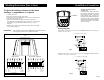
The pump should never be located at the lowest point of the piping system, where dirt and
sediment collect. Nor should it be located at the highest point of the piping sytem, where
air accumulates.
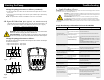
WARNING: Never make any connections in the pump terminal box unless
the electrical supply has been switched off.
AVERTISSEMENT: Ne jamais établir de connexions dans la boîte de
jonction de la pompe à moins que l’alimentation électrique n’ait été coupée.
Fig.1
Page 3 Page 16
Replacing Components
Replacing the Pump Head
Removal
1. Disconnect or TURN OFF the power supply.
2. Close any isolation valves on either side of the pump to avoid draining
the system of liquid.
3. Disconnect the electrical leads from the terminal box.
4. Disconnect and remove the conduit from the terminal box.
5. Loosen and remove the four allen screws (8 or 10 mm) which connect
the pump head housing to the pump housing.
6. Remove the pump head from the pump housing.
7. Clean the machined surfaces in the pump housing of any foreign
material.
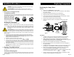
Installation
1. Carefully remove the new pump head assembly from its packaging.
Separate the impeller/rotor assembly from the new pump head.
2. While holding the thrust bearing, carefully place the impeller/rotor
assembly into the pump housing. The bearing plate should fit snugly into
the lowest machined surface in the pump housing.
3. Make sure that the impeller/rotor assembly can rotate freely.
4. Place the O-Ring over the rotor and locate it into the inner diameter of
the pump housing.
5. Carefully place the pumphead housing over the rotor and rotate it so the
terminal box is in the position you wish (see page 3 for positioning).
6. Make sure the pump head housing is properly seated on the pump
housing. Do not force the two together -- if there is binding,
disassemble them and repeat steps 2-6. Tighten the allen screws evenly
to secure the pump head.
Torque to: 8mm ............. 15 ft lbs
10mm ............. 25 ft lbs
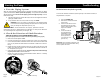
7. Check to make sure the motor shaft turns freely, as explained in step 5
on page 3 (under "Rotating the Terminal Box").
Fig. 21