
Installation Guide

Page 17
Pre-Installation Checklist
4. Pumped Liquid Requirements
CAUTION: This pump is intended for use with water only.
Your VersaFlo UPS pump can be used to circulate:
• Potable hot water
• Water for hydronic heating
• Cooling water
• In domestic hot water systems it is advisable to use bronze pumps (VersaFlo UPS
model) only for water with a degree of hardness lower than 14 grains per gallon of
hardness. For water with a higher degree of hardness, a direct coupled VersaFlo
TP pump is recommended.
• If the pump is installed in a heating system, the water should meet the requirements
of accepted standards on water quality in heating systems.
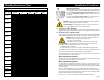
The pump is lubricated and cooled by the liquid being pumped. Therefore, the pumped
liquid must always be allowed to circulate through the pump. Extended periods without
circulation will cause premature wear to the bearings and excessive motor heat. The
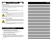
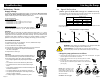
pumped liquid must also meet the following requirements:
MINIMUM PUMP
INLET PRESSURE
(During Operation)
LIQUID
TEMPERATURE
RANGE
Continuously: 14°F (-10°C)
up to 230°F (110°C)
Intermittent: < 284°F (140°C)
for short periods of time.
Domestic Hot Water:
<140°F (60°C)
At These Liquid Temps
UPS 167°F 194°F 230°F
Model 75°C 90°C 110°C
[psi] hf [psi] hf [psi] hf
32-40 0.7 1.6 2.2 5.1 21.0 48.5
32-80 0.7 1.6 5.1 11.8 23.9 55.2
32-160 11.6 26.8 16.0 37.0 34.1 78.8
40-40 0.7 1.6 4.4 10.2 23.2 53.6
40-80/4 0.7 1.6 1.5 3.5 18.1 41.8
40-80/2 6.5 15.0 10.9 25.2 29.0 67.0
40-160 5.1 11.8 9.4 21.7 27.6 63.8
40-240 11.6 26.8 16.0 37.0 34.1 78.8
50-40 0.7 1.6 2.9 6.7 21.8 50.4
50-80/4 0.7 1.6 4.4 10.2 23.2 53.6
50-80/2 4.4 10.2 8.7 20.1 26.8 61.9
50-160 11.6 26.8 16.0 37.0 34.1 78.8
50-240 10.2 23.6 14.5 33.5 32.6 75.3
80-40 11.6 26.8 16.0 37.0 34.1 78.8
80-80 14.5 33.5 18.9 43.7 37.0 85.5
80-160 21.8 50.4 26.1 60.3 43.5 100.5
100-40 27.6 63.8 31.9 73.7 50.0 115.5
Page 2
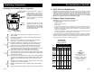
3. Verify Electrical Requirements
Verification of the electrical supply should be made to be certain the voltage, phase and
frequency match that of the pump motor. The proper operating voltage and other electrical
information can be found on the motor nameplate. These motors are designed to run on
±10% of the nameplate-rated voltage. Wiring connection diagrams can be found inside
the terminal box cover and later in these Installation and Operating Instructions. If voltage
variations are larger than ±10%, do not operate the pump.
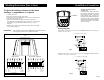
1. Before replacing the terminal box or capacitor, make sure the
power is OFF.
2. Remove the terminal box cover by completely loosening all four
torx/standard screws.
3. Remove the speed switch (noting its position) by pulling firmly
and evenly on both sides of it. (Not for 460/575 V)
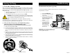
a.4. (Capacitor replacement, single-phase only) Disconnect the two
connector clips from the capacitor and unscrew the complete
plastic strain relief nut. Remove capacitor wire and strain relief.
a.5. Screw in new complete strain relief nut and connect new clip
connectors. Pull excess sheathed cable out of terminal box, being
sure to leave at least
1
/
8
" of sheath inside of terminal box.
b.4. (Terminal box replacement, single-phase and three-phase)
Disconnect all wiring, remove the three phillips-head screws holding
the terminal box in place and remove the terminal box by pulling firmly
and evenly on both side.
b.5. Check that the clear rubber gasket is in place around the terminal box
connector stem, carefully press the terminal box into the stator socket,
replace the three phillips-head terminal box screws and replace
wiring.
6. Replace the speed switch to its proper position, making sure to push
it all the way in. (Not for 460/575V)
7. Replace the terminal box cover and tighten all four torx/standard
screws.
8. Switch on electrical power supply. The pump is now ready for operation.
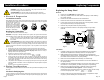
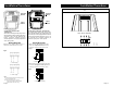
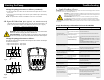
Replacing Components
Replacing the Terminal Box or Capacitor
If the terminal box is replaced,
make certain the electrical in-
formation listed on the new box
matches the information listed on
the old box, and that it is compatible
with the pump and incoming
electrical supply.
For all terminal boxes, it is very
important to tightly secure the
frame ground-ing screw through
the terminal box, so that a proper
connection between the terminal
box and motor is made.
Speed
Switch
Standard
Module
Electrical
Information
Frame Ground
Screw Hole
All
{
{
{
{
Capacitor
Terminal
Box
All
Fig.22