
Installation Guide

L3
L1
L2
P1
P2
T5
T4 T6
T3 T2 T1
L3
L1
L2
P1
P2
T5
T4 T6
T3 T2 T1
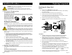
Change the pump performance as follows: (continued)
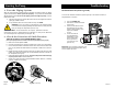
4. Fit the terminal box cover back onto the terminal box and tighten the four screws
in the cover.
5. Switch on the electrical supply. Check that the green indicator light is permanently
on or flashing.
NOTE: The speed switch module must never be used as an on/off switch.
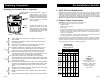
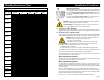
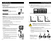
3b. Speed Selection (two speed, 3 x 460V & 575V)
The speed setting in the terminal box (see Fig.13) can be changed to two positions. The
speed in the two positions appears in the table below (also see Fig.13 on page 8).
Speed Step Speed in % of Maximum Speed
1 approx. 75%
2 100%
WARNING: Never make any connections in the pump terminal box
unless the electrical supply has been switched off.
AVERTISSEMENT: Ne jamais établir de connexions dans la boîte de
jonction de la pompe à moins que l’alimentation électrique n’ait été coupée.
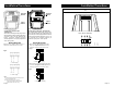
Change the pump performance as follows:
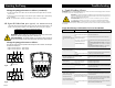
The speed is changed by the position of the bridges in the terminals. The bridges
are fitted according to:
• Figure 15 for speed 1 - Low speed
• Figure 16 for speed 2 - High speed
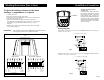
Starting the Pump
Fig.16
Fig.15
L1
L2
L3
P1
P2
T6
T4
T5
T1
T2
T3
Fig.17
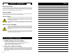
Troubleshooting
1. Fault Finding Chart
WARNING: Before removing the terminal box cover, make sure that the electrical supply has been switched
off and that it cannot be accidentally switched on.
WARNING: The pumped liquid may be scalding hot and under high pressure. Before any
removal or dismantling of the pump, the system must be drained or the isolating valves on
both sides of the pump must be closed.
AVERTISSEMENT: Avant de retirer le couvercle de la boîte de jonction, s’assurer
que l’alimentation électrique a été coupée et ne peut être rétablie accidentellement.
AVERTISSEMENT: Le liquide pompé peut être brûlant et sous haute pression. Avant de
retirer ou de démonter la pompe, il faut drainer le système ou fermer les deux robinets d’isolement latéraux
de la pompe.
Single-Head Pumps with Standard or Protection Module
Fault
The pump does not run.
None of the indicator lights are
on.
The pump does not run.
The green indicator light is on.
Three-Phase Pumps Only:
The pump is running. The red
and green indicator lights are on.
Noise in the system. The green
indicator light is on.
Noise in the pump. The green
indicator light is on.
Insufficient heat in some places
in the heating system.
Single phase pumps with
protection module (only).
The Pump does not run.
The red indicator light is on.
The green indicator light is off.
Cause
One fuse in the installation is blown.
External circuit breaker is switched
off.
Current/Voltage operated ground
fault interrupter has tripped.
The pump's internal thermal
overload switch has cut out
( Standard module only).
Rotor blocked, but the pump hasn't
been cut out by the thermal overload
switch.
The speed switch module has not
been fitted.
The pump is running with the wrong
direction of rotation.
Air in the system.
The pump flow is too high.
The pressure is too high.
Air in the pump.
The inlet pressure is too low.
The pump performance is too low.
The pump has been cut out by the
thermal overload switch due to high
liquid temperature or blocked rotor.
The speed switch module has not
been fitted.
Remedy
Replace the fuse.
Switch the circuit breaker on.
Repair the insulation defects and reset the circuit breaker.
Check that the liquid temperature falls within the specified
range.
With external on/off changeover contact: The pump will
restart automatically when it has cooled to the normal
temperature.
With external on/off impulse contacts: The pump can be
restarted when it has cooled to normal temperature.
Switch off the electricity supply and clean/repair the pump.
Switch off the electricity supply at the external circuit breaker
and fit the speed switch module into position.
Switch off the electricity supply at the external circuit breaker
and interchange any two phases (leads) in the pump terminal
box.
Vent the system.
Reduce the pump performance.
Reduce the pump performance.
Vent the pump.
Increase the inlet pressure and/or check the air volume in the
expansion tank (if installed).
Increase the pump performance, if possible, or replace the
pump with a pump with higher flow.
Check that the liquid temperature falls within the specied
range.The pump will restart automatically when it has cooled
to normal temperature.
Note: If the thermal overload switch has cut out the pump three
times within a short period, the pump must be restarted
manually by switching off the electrical suply.
Switch off the electrical supply by means of the external mains
switch and fit the speed switch module.
Page 10
Page 9
Jumper Wire
Jumper Wire