
Installation Guide

Examine the components carefully to make sure no
damage has occurred to the pump during shipment. Care
should be taken to ensure the pump is NOT dropped or
mishandled; dropping will damage the pump.
Shipment Inspection
Before beginning installation procedures, the
following checks should be made. They are all
important for proper installation of the circulator
pump.
1. Uses:
Model UPS 15, and UP15, 25, 26 and 43 series pumps
are designed to circulate water from 50°F to 230°F up to
a maximum pressure of 145 psi. If required, a 50% by
volume solution of ethylene or propylene glycol and water
can be used, however, a decrease in pump performance
may result due to an increase in the viscosity of the
solution. Check with manufacturer for information
regarding suitability of pumping other fluids.
Closed Systems: UPS 15 and UP 26 and 43 series
pumps with cast iron volutes are recommend for closed
hydronic systems (i.e. airless, non-potable water).
Open Systems: UP 15, 25, 26 and 43 series pumps
with stainless steel or bronze volutes can be used in both
open and closed systems.
2. Maximum Water Temperature:
The maximum allowable water temperature is determined
by the ambient or surrounding air temperature as shown
in Table 2A.
Table 2A – Maximum Water Temperature
Ambient (°F) 104 120 140 160 175
Water (°F) 230 220 210 190 175
3. Inlet Pressure Requirements
The amount of pressure required at the inlet of the pump
is a function of the temperature of the water as shown in
Table 2B.
Pre-Installation
Checklist
Table 2B – Inlet Pressure Requirements
Water (°F) 190 165 140
Required Inlet Pressure (ft.) 5 4.5 3
(psi) 2.2 1.9 1.3
In a pressurized system, the required inlet pressure is the
minimum allowable system pressure.
In a system open to the atmosphere, the required inlet
pressure is the minimum distance the pump must be
located below the lowest possible water level of the water
source (tank, pool, etc.).
Installation
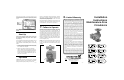
Position of terminal box:
Proper installation of the pump will have the terminal box
located to one side of the pump or the other, with the
conduit entry down. See Figure 3A.
If the terminal box position needs to be changed, it is best
to do so before installation. However, if the pump is
already installed, ensure that the electrical supply is turned
off and close the isolation valves before removing the Allen
screws.
To change terminal box position:
1. Remove the four (4) Allen screws (4 or 5mm wrench)
while supporting the stator (motor).
2. Carefully separate the stator from the pump chamber
and rotate it to the correct terminal box orientation.
3. Replace the Allen screws and tighten diagonally and
evenly (7 ft.-lb. torque).
4. Check that the motor shaft turns freely. Remove the
large screw in the middle of the nameplate, insert a
small flat blade screwdriver into the end of the shaft,
and turn gently.
If the shaft does not turn easily, repeat the disassembly/
reassembly process.
NOTE: UPS15-42 does not require manual turning of
shaft.
Pump Mounting: For Indoor Use
Arrows on the side or bottom of the pump chamber indicate
direction of flow through the pump. GRUNDFOS
circulators can be installed in both vertical and horizontal
lines. The pump must be installed with the motor shaft
positioned horizontally.
Under no circumstances should
the pump be installed with the shaft vertical or where the
shaft falls below the horizontal plane. See Figure 3B.
It is recommend that isolation valves be installed on each
side of the pump. If possible, do not install elbows, branch
tees, and similar fittings just before or after the pump.
Provide support to the pump or adjacent plumbing to
reduce thermal and mechanical stress on the pump.
Installation Requirements
1. Thoroughly clean and flush the system prior to pump
installation.
2. Do not install the pump at the lowest point of the system
where dirt and sediment naturally collect.
3. Install an air vent at the high point(s) of the system to
remove accumulated air.
4. Ensure that water does not enter the terminal box
during the installation process.
5. (Open System) Install the pump in the supply line; the
suction side of the pump should be flooded with water.
Ensure that the static head requirement from Table 2B
is achieved.
6. (Closed System) Install a safety relief valve to protect
against temperature and pressure build-up.
7. If there are excessive suspended particles in the water,
it is recommended that a strainer and/or filter be
installed and cleaned regularly.
8. DO NOT START THE PUMP UNTIL THE SYSTEM
HAS BEEN FILLED.
Electrical
Wiring diagram for all 115V and 230V models
(except UPS15-42F).
4.
3.
2.
1.
Figure 3A
Recommended Terminal Box Orientation
All electrical work should be performed by a qualified
electrician in accordance with the latest edition of the
National Electrical Code, local codes and regulations.
Warning:
The safe operation of this pump requires that it be
grounded in accordance with the National Electrical Code
and local governing codes or regulations. The ground
wires should be copper conductor of at least the size of
the circuit conductor supplying power to the pump.
Minimum ground wire size is 14 AWG. Connect the ground
wire to the grounding point in the terminal box and then to
an acceptable ground. Do not ground to a gas supply
line.
The proper operating voltage and other electrical
information can be found on the nameplate attached to
the top of the motor. Depending on pump model, the motor
has either built-in, automatic resetting thermal protection
or is impedance protected and in either case does not
require additional external protection. The temperature
of the windings will never exceed allowable limits, even if
the rotor is locked.
Wire sizes should be based on the ampacity (current
carrying properties of a conductor) as required by the latest
edition of the National Electrical Code or local regulations.
Both the power and grounding wires must be suitable for
at least 194°F (90°C).
For all 115V and 230V models: Connect the white/yellow electrical
leads from the circulator to the incoming power leads with wire
nuts or other approved connectors. Attach incoming grounding
wire to either of the green grounding screws.
Figure 3B
Acceptable Unacceptable
Page 1
Page 2
Page 3 Page 4