
Submittal Sheet
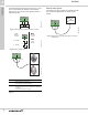
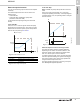
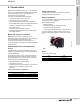
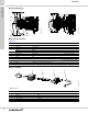
Table Of Contents
- 1. Product description
- 2. Product range
- 3. System applications
- 4. Functions
- Control modes: Quick overview
- Operating modes
- Control modes
- Additional control mode features
- Multipump modes
- Flow estimation accuracy
- Readings on the pump
- Performance overview
- Operating status and pump performance
- Warning and alarm
- Heat energy monitor
- Heat consumption accuracy
- Operating log
- Help and guidance
- Grundfos Eye
- Communication
- Grundfos GO Remote
- Wireless GENIair
- CIM modules
- Available CIM modules
- Grundfos Remote Management
- Digital inputs
- Relay outputs
- Analog input for an external sensor
- External setpoint function
- 5. Operating conditions
- 6. Construction
- 7. Installation
- 8. Operating the product
- 9. Curve conditions
- 10. Performance curves and technical data
- Conversion tables
- MAGNA3 32-60 F (N)
- MAGNA3 32-100 F (N)
- MAGNA3 32-120 F (N)
- MAGNA3 40-80 F (N)
- MAGNA3 40-120 F (N)
- MAGNA3 40-180 F (N)
- MAGNA3 50-80 F (N)
- MAGNA3 50-120 F (N)
- MAGNA3 50-150 F (N)
- MAGNA3 50-180 F (N)
- MAGNA3 65-120 F (N)
- MAGNA3 65-150 F (N)
- MAGNA3 D 65-150 F
- MAGNA3 80-100 F (N)
- MAGNA3 D 80-100 F
- MAGNA3 100-120 F (N)
- MAGNA3 D 100-120 F
- 11. Accessories
- 12. Product numbers
- 13. Grundfos Product Center

Operating conditions
MAGNA3
5
36
Electrical data
* All MAGNA3 pumps are approved to run on both 50 and 60 Hz.
Sound pressure level
The sound pressure level of the pump is dependent on
the power consumption. Levels are determined in
accordance with ISO 3745 and ISO 11203, method Q2.
Note: Not all variants are available in all markets.
Pump type MAGNA3 (D)
Enclosure class Type 2
Insulation class F.
Supply voltage
1 x 115-230 V ± 10 %, 60 Hz*, PE.
M20 cable gland (supplied with the pump).
Three digital inputs
External potential-free contact.
Contact load: 5 V, 10 mA.
Screened cable.
M16 cable gland (not supplied with the pump).
Loop resistance: Maximum 130 Ω.
Analog input
4-20 mA (load: 150 Ω).
0-10 VDC (load: > 10 kΩ).
Two relay outputs
Internal potential-free changeover contact.
Maximum load: 250 V, 2 A, AC1.
Minimum load: 5 VDC, 20 mA.
Screened cable, depending on signal level.
M16 cable gland (not supplied with the pump).
Bus input
Grundfos Communication Interface Modules (add-on CIM modules) for:
• GENIbus
• LonWorks+
• Modbus RTU
• BACnet MS/TP
• GSM/GPRS
• Grundfos Remote Management
• Ethernet.
Leakage current
I
leakage
< 3.5 mA.
The leakage currents are measured in accordance with EN 60335-1.
EMC
Standards used: EN 55014-1:2006 + A1:2009 + A2:2011, EN 55014-1:2017, EN 61000-6-2:2005, EN
61000-3-3:2013, EN61000-3-2:2014.
Cos φ
Terminal-connected versions have a built-in active PFC (Power Factor Control) which gives a cos φ from 0.98 to
0.99, i.e. very close to 1.
Wire-to-wire versions have no PFC and therefore the power factor is from 0.50 to 0.99.
Consumption when the pump is
stopped
4 to 10 W, depending on activity, i.e. reading the display, use of Grundfos GO, interaction with modules, etc.
4 W, when the pump is stopped and there is no activity.
Pump size Maximum dB(A)
25-40/60/80/100/120
32-40/60/80/100/120
40-40/60
50-40
39
32-120 F
40-80/100
50-60/80
65-40/60
80-40
45
40-120/150/180
50-100/120/150/180
65-80/100/120
80-60/80
100-40/60
50
65-150
80-100/120
100-80/100/120
55