
Submittal Sheet
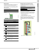
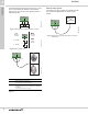
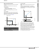
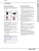
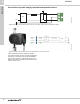
Table Of Contents
- 1. Product description
- 2. Product range
- 3. System applications
- 4. Functions
- Control modes: Quick overview
- Operating modes
- Control modes
- Additional control mode features
- Multipump modes
- Flow estimation accuracy
- Readings on the pump
- Performance overview
- Operating status and pump performance
- Warning and alarm
- Heat energy monitor
- Heat consumption accuracy
- Operating log
- Help and guidance
- Grundfos Eye
- Communication
- Grundfos GO Remote
- Wireless GENIair
- CIM modules
- Available CIM modules
- Grundfos Remote Management
- Digital inputs
- Relay outputs
- Analog input for an external sensor
- External setpoint function
- 5. Operating conditions
- 6. Construction
- 7. Installation
- 8. Operating the product
- 9. Curve conditions
- 10. Performance curves and technical data
- Conversion tables
- MAGNA3 32-60 F (N)
- MAGNA3 32-100 F (N)
- MAGNA3 32-120 F (N)
- MAGNA3 40-80 F (N)
- MAGNA3 40-120 F (N)
- MAGNA3 40-180 F (N)
- MAGNA3 50-80 F (N)
- MAGNA3 50-120 F (N)
- MAGNA3 50-150 F (N)
- MAGNA3 50-180 F (N)
- MAGNA3 65-120 F (N)
- MAGNA3 65-150 F (N)
- MAGNA3 D 65-150 F
- MAGNA3 80-100 F (N)
- MAGNA3 D 80-100 F
- MAGNA3 100-120 F (N)
- MAGNA3 D 100-120 F
- 11. Accessories
- 12. Product numbers
- 13. Grundfos Product Center

Functions
MAGNA3
4
33
External setpoint function
You can use the analog input to influence the setpoint
externally.
The external setpoint function can be used in two
different ways:
• Linear with Min.
• Linear with Stop (available for pumps with
production code from 1838)
In both modes the input signal range is influenced
linearly.
Linear with Min.
Here, a 0-10 V or 4-20 mA signal controls the pump
speed range in a linear function. The range of control
depends on the minimum speed, power and pressure
limits of the pump. See figs 45 and 46.
Fig. 45 Linear with Min., 0-10 V
Fig. 46 Control range and setpoint
Linear with Stop
Note: Available for pumps with production code from
1838.
Here, if the input signal is below 10 %, the pump
changes to operating mode "Stop". If the input signal is
increased above 15 %, the operating mode is changed
back to "Normal".
Fig. 47 "Linear with Stop", 0-10 V
External setpoint function according to model
The external setpoint function operates differently,
depending on the model. For model A,B and C, the
maximum speed is often obtained at voltages lower
than 10 V as the span of control is limited.
In models newer than A,B, and C, the internal scaling
has been optimised making the dynamic area bigger,
thus giving a better control of the pump speed when
using the external setpoint function.
The same applies if the pump is receiving a set point
from Building Management Systems.
TM06 9149 2117
Control
0-2 V (0-20 %) Resulting setpoint is equal to minimum.
2-10 V (20-100 %)
Resulting setpoint is between minimum and
user setpoint.
V
1020
H
(user setpoint)
Analog input
Resulting
setpoint
TM06 9149 2117
10 V
20 mA
20
H
4
Stop
Normal