
Submittal Sheet
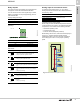
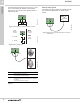
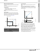
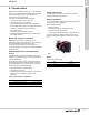
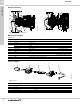
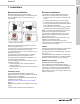
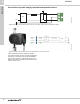
Table Of Contents
- 1. Product description
- 2. Product range
- 3. System applications
- 4. Functions
- Control modes: Quick overview
- Operating modes
- Control modes
- Additional control mode features
- Multipump modes
- Flow estimation accuracy
- Readings on the pump
- Performance overview
- Operating status and pump performance
- Warning and alarm
- Heat energy monitor
- Heat consumption accuracy
- Operating log
- Help and guidance
- Grundfos Eye
- Communication
- Grundfos GO Remote
- Wireless GENIair
- CIM modules
- Available CIM modules
- Grundfos Remote Management
- Digital inputs
- Relay outputs
- Analog input for an external sensor
- External setpoint function
- 5. Operating conditions
- 6. Construction
- 7. Installation
- 8. Operating the product
- 9. Curve conditions
- 10. Performance curves and technical data
- Conversion tables
- MAGNA3 32-60 F (N)
- MAGNA3 32-100 F (N)
- MAGNA3 32-120 F (N)
- MAGNA3 40-80 F (N)
- MAGNA3 40-120 F (N)
- MAGNA3 40-180 F (N)
- MAGNA3 50-80 F (N)
- MAGNA3 50-120 F (N)
- MAGNA3 50-150 F (N)
- MAGNA3 50-180 F (N)
- MAGNA3 65-120 F (N)
- MAGNA3 65-150 F (N)
- MAGNA3 D 65-150 F
- MAGNA3 80-100 F (N)
- MAGNA3 D 80-100 F
- MAGNA3 100-120 F (N)
- MAGNA3 D 100-120 F
- 11. Accessories
- 12. Product numbers
- 13. Grundfos Product Center

Functions
MAGNA3
4
31
Relay outputs
The pump has two signal relays with a potential-free
changeover contact for external fault indication.
You can set the function of the signal relay to Alarm,
Ready or Operation on the pump operating panel or
with Grundfos GO.
Factory settings of relays:
Note: You can configure both relays to "ready, alarm or
operating".
Fig. 39 Relay output in the control box
The functions of the signal relays are as shown in the
table below:
Analog input for an external sensor
To optimize pump performance, you can use the
analog input for the connection of an external sensor in
the following cases:
Controlling the flow in the system
When using an external differential-pressure sensor to
control the flow in the system, you obtain the externally
set pressure, which results in the following benefits:
• minimizes operating costs
• prevents valve noise
• ensures comfort (adequate pressure).
When setting this function, make sure that the pump is
set to run in constant-pressure mode and that
"Differential-pressure control" has been activated in
the "Analog input" menu on the pump's operating
panel.
Fig. 40 External differential-pressure sensor
Relay Function
1 Operation signal
2 Alarm signal
TM05 3343 1212
Contact symbol Function
NC Normally closed
NO Normally open
CCommon
Signal relay Alarm signal
Not activated:
• The power supply has been switched off.
• The pump has not registered a fault.
Activated:
• The pump has registered a fault.
Signal relay Ready signal
Not activated:
• The pump has registered a fault and is unable to
run.
Activated:
• The pump has been set to stop, but is ready to
run.
• The pump is running.
Signal relay Operating signal
Not activated:
• The pump is not running.
Activated:
• The pump is running.
NC N0 C
S/S
M
I
M
A
132
NC NO C
132
NC NO C
12 3
NC NO C
132
NC NO C
132
NC NO C
12 3
NC NO C
132
NC NO C
132
NC NO C
12 3
NC NO C
Function/control mode Sensor type
Heat energy monitor
Temperature sensorConstant temperature
Differential temperature
Constant pressure Differential-pressure transmitter
TM07 0361 1218
T
T