
Submittal Sheet
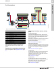
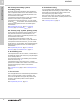
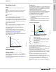
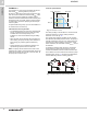
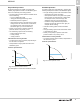
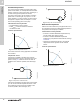
Table Of Contents
- 1. Product description
- 2. Product range
- 3. System applications
- 4. Functions
- Control modes: Quick overview
- Operating modes
- Control modes
- Additional control mode features
- Multipump modes
- Flow estimation accuracy
- Readings on the pump
- Performance overview
- Operating status and pump performance
- Warning and alarm
- Heat energy monitor
- Heat consumption accuracy
- Operating log
- Help and guidance
- Grundfos Eye
- Communication
- Grundfos GO Remote
- Wireless GENIair
- CIM modules
- Available CIM modules
- Grundfos Remote Management
- Digital inputs
- Relay outputs
- Analog input for an external sensor
- External setpoint function
- 5. Operating conditions
- 6. Construction
- 7. Installation
- 8. Operating the product
- 9. Curve conditions
- 10. Performance curves and technical data
- Conversion tables
- MAGNA3 32-60 F (N)
- MAGNA3 32-100 F (N)
- MAGNA3 32-120 F (N)
- MAGNA3 40-80 F (N)
- MAGNA3 40-120 F (N)
- MAGNA3 40-180 F (N)
- MAGNA3 50-80 F (N)
- MAGNA3 50-120 F (N)
- MAGNA3 50-150 F (N)
- MAGNA3 50-180 F (N)
- MAGNA3 65-120 F (N)
- MAGNA3 65-150 F (N)
- MAGNA3 D 65-150 F
- MAGNA3 80-100 F (N)
- MAGNA3 D 80-100 F
- MAGNA3 100-120 F (N)
- MAGNA3 D 100-120 F
- 11. Accessories
- 12. Product numbers
- 13. Grundfos Product Center

System applications
MAGNA3
3
13
Ground source heat pump systems
(GSHP)
Fig. 12 Ground source heat pump system in a commercial
building
The following sections provide recommendations on
which control mode to choose according to your
application and where the pump is placed in the
system.
In addition, you can use MAGNA3's built-in application
wizard to help you identify which control mode is best
suited your application. See Application wizard, page
42.
1. Charging pump
If the temperature in the tank falls below a certain
threshold, the charging pump starts. The pump
operates until the tank temperature is back up at the
desired level.
As this is a closed circuit with no flow variations,
constant-flow or constant-curve operation are suitable
control modes.
See Constant flow, page 21 and Constant curve, page
21.
2. Distribution side
If the distribution pump is connected to a radiator
system, proportional pressure is the optimum control
mode. If underfloor heating is connected right after the
pump, constant pressure is preferred.
See Proportional pressure, page 19, and Constant
pressure, page 19.
3. Ground loop
Since the ground loop is a closed system with no
variations in flow, the most suitable control modes are
constant flow and constant curve.
See Constant flow, page 21 and Constant curve, page
21.
Solar-heating systems
Fig. 13 Functional drawing of a solar-heating system
We recommend that the main pump in a solar-heating
system operates with the constant-curve control mode
or as recommended by the solar system provider.
Alternative control modes, like constant temperature or
differential temperature, can be viable options, but the
must only be chosen based on dialogue with the solar
system provider.
See Constant curve, page 21, Constant temperature,
page 20, and Differential temperature, page 20.
TM07 0359 1218
Pos. Description
1 Charging pump
2 Distribution side
3 Ground loop
T
12
3
TM07 0367 1218
T