
Submittal Sheet
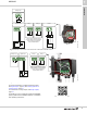
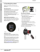
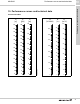
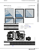
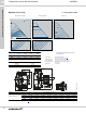
Table Of Contents
- 1. Product description
- 2. Product range
- 3. System applications
- 4. Functions
- Control modes: Quick overview
- Operating modes
- Control modes
- Additional control mode features
- Multipump modes
- Flow estimation accuracy
- Readings on the pump
- Performance overview
- Operating status and pump performance
- Warning and alarm
- Heat energy monitor
- Heat consumption accuracy
- Operating log
- Help and guidance
- Grundfos Eye
- Communication
- Grundfos GO Remote
- Wireless GENIair
- CIM modules
- Available CIM modules
- Grundfos Remote Management
- Digital inputs
- Relay outputs
- Analog input for an external sensor
- External setpoint function
- 5. Operating conditions
- 6. Construction
- 7. Installation
- 8. Operating the product
- 9. Curve conditions
- 10. Performance curves and technical data
- Conversion tables
- MAGNA3 32-60 F (N)
- MAGNA3 32-100 F (N)
- MAGNA3 32-120 F (N)
- MAGNA3 40-80 F (N)
- MAGNA3 40-120 F (N)
- MAGNA3 40-180 F (N)
- MAGNA3 50-80 F (N)
- MAGNA3 50-120 F (N)
- MAGNA3 50-150 F (N)
- MAGNA3 50-180 F (N)
- MAGNA3 65-120 F (N)
- MAGNA3 65-150 F (N)
- MAGNA3 D 65-150 F
- MAGNA3 80-100 F (N)
- MAGNA3 D 80-100 F
- MAGNA3 100-120 F (N)
- MAGNA3 D 100-120 F
- 11. Accessories
- 12. Product numbers
- 13. Grundfos Product Center

Installation
MAGNA3
7
41
Fig. 55 Example of connections in the control box of terminal-connected versions
Fig. 56 Example of connections in the control box of wire-to-wire connected versions
For further information on digital and analog inputs,
see Digital inputs, page 30, and Analog input for an
external sensor, page 31.
For information on relay outputs, see Relay outputs,
page 31.
For details on how to install and operate the MAGNA3
pumps, please see the MAGNA3 model D - Installation
and operating instructions:
TM07 0364 1518
LN
L
N
NC NO
C
NC NO
C
S/S
M
A
M
I
24V
IN
Power
Operation
Alarm
Analog input
Relay 1 Relay 2Digital input
GFCI
Vcc
Signal
Sensor
Use C and NC for fault signals
as this enables serial connections
of more relays and detection
of signal cable defects.
Start/stop
On/off
timer
TM07 1623 1918
NC NO
C
NC NO
C
S/S
M
A
M
I
24V
IN
Analog input
Digital input
Relay 1
Relay 2
Operation
Alarm
Vcc
Signal
Sensor
Use C and NC for fault signals
as this enables serial connections
of more relays and detection
of signal cable defects.
net.grundfos.com/qr/i/99332342