
Submittal Sheet
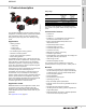
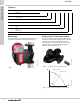
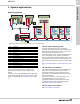
Table Of Contents
- 1. Product description
- 2. Product range
- 3. System applications
- 4. Functions
- Control modes: Quick overview
- Operating modes
- Control modes
- Additional control mode features
- Multipump modes
- Flow estimation accuracy
- Readings on the pump
- Performance overview
- Operating status and pump performance
- Warning and alarm
- Heat energy monitor
- Heat consumption accuracy
- Operating log
- Help and guidance
- Grundfos Eye
- Communication
- Grundfos GO Remote
- Wireless GENIair
- CIM modules
- Available CIM modules
- Grundfos Remote Management
- Digital inputs
- Relay outputs
- Analog input for an external sensor
- External setpoint function
- 5. Operating conditions
- 6. Construction
- 7. Installation
- 8. Operating the product
- 9. Curve conditions
- 10. Performance curves and technical data
- Conversion tables
- MAGNA3 32-60 F (N)
- MAGNA3 32-100 F (N)
- MAGNA3 32-120 F (N)
- MAGNA3 40-80 F (N)
- MAGNA3 40-120 F (N)
- MAGNA3 40-180 F (N)
- MAGNA3 50-80 F (N)
- MAGNA3 50-120 F (N)
- MAGNA3 50-150 F (N)
- MAGNA3 50-180 F (N)
- MAGNA3 65-120 F (N)
- MAGNA3 65-150 F (N)
- MAGNA3 D 65-150 F
- MAGNA3 80-100 F (N)
- MAGNA3 D 80-100 F
- MAGNA3 100-120 F (N)
- MAGNA3 D 100-120 F
- 11. Accessories
- 12. Product numbers
- 13. Grundfos Product Center

System applications
MAGNA3
3
9
3. System applications
Heating systems
Fig. 10 Functional drawing of a heating system in a commercial building
The following sections provide recommendations on
which control mode to choose according to your
application and where the pump is placed in the
system.
In addition, you can use MAGNA3's built-in application
wizard to help you identify which control mode is best
suited your application. See Application wizard, page
42.
1A. Hot water, charging pump
Hot-water applications often have an external
controller, which starts the pump when the temperature
falls below a desired setpoint. The pump will run until
the temperature in the tank is back up.
If the design flow is known, it can be set directly on the
pump. The suitable control mode is constant flow.
If only the desired differential temperature across the
plate heat exchanger is known, constant speed curves
can be chosen and adjusted to reach the desired delta
T.
See Constant flow, page 21, and Constant curve, page
21.
1B. Hot water, recirculation
The constant-temperature control mode together with
the pump's internal temperature sensor makes it
possible to maintain any given temperature of the
return water. The desired temperature setpoint is set
directly on the pump.
If you want to maintain a certain temperature at a
critical point furthest out in the system, the
constant-temperature control mode can be used in
combination with an external temperature sensor.
See Constant temperature, page 20.
2A. Hot water, recirculation
See 1B. Hot water, recirculation.
TM07 0360 1218
MMMMM
T
T
M
2
4
A
B
C
13
567
8
D
E
Pos. Description
1 Hot water
1A Charging pump
1B Recirculation
2 Hot water
2A Recirculation
3 Air handling unit
4 Fan coil unit
5 Radiator two-pipe system
6 Radiator one-pipe system
7 Underfloor/ceiling
8 Boiler pump
8D Shunt/buffer
8E 'Primary only' system