
Submittal Sheet
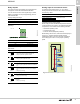
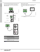
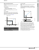
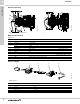
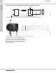
Table Of Contents
- 1. Product description
- 2. Product range
- 3. System applications
- 4. Functions
- Control modes: Quick overview
- Operating modes
- Control modes
- Additional control mode features
- Multipump modes
- Flow estimation accuracy
- Readings on the pump
- Performance overview
- Operating status and pump performance
- Warning and alarm
- Heat energy monitor
- Heat consumption accuracy
- Operating log
- Help and guidance
- Grundfos Eye
- Communication
- Grundfos GO Remote
- Wireless GENIair
- CIM modules
- Available CIM modules
- Grundfos Remote Management
- Digital inputs
- Relay outputs
- Analog input for an external sensor
- External setpoint function
- 5. Operating conditions
- 6. Construction
- 7. Installation
- 8. Operating the product
- 9. Curve conditions
- 10. Performance curves and technical data
- Conversion tables
- MAGNA3 32-60 F (N)
- MAGNA3 32-100 F (N)
- MAGNA3 32-120 F (N)
- MAGNA3 40-80 F (N)
- MAGNA3 40-120 F (N)
- MAGNA3 40-180 F (N)
- MAGNA3 50-80 F (N)
- MAGNA3 50-120 F (N)
- MAGNA3 50-150 F (N)
- MAGNA3 50-180 F (N)
- MAGNA3 65-120 F (N)
- MAGNA3 65-150 F (N)
- MAGNA3 D 65-150 F
- MAGNA3 80-100 F (N)
- MAGNA3 D 80-100 F
- MAGNA3 100-120 F (N)
- MAGNA3 D 100-120 F
- 11. Accessories
- 12. Product numbers
- 13. Grundfos Product Center

Construction
MAGNA3
6
37
6. Construction
MAGNA3 is of the canned-rotor type, i.e. the pump and
motor form an integral unit without shaft seal and with
only two gaskets for sealing. The bearings are
lubricated by the pumped liquid.
The pump is characterized by the following:
• controller integrated in the control box
• operating panel on the control box
• control box prepared for optional CIM modules
• built-in differential-pressure and temperature sensor
• cast-iron or stainless-steel pump housing
• twin-head versions
• no external motor protection required
• insulating shells supplied with single-head pumps
for heating systems.
Motor and electronic controller
MAGNA3 incorporates a 4-pole synchronous,
permanent-magnet motor (PM motor). This motor type
is characterized by higher efficiency than a
conventional asynchronous squirrel-cage motor.
The pump speed is controlled by an integrated variable
frequency drive.
Differential-pressure and temperature
sensor
The differential-pressure and temperature sensor is
located in the pump housing in a channel between the
inlet and outlet ports.
Via a cable, the sensor sends an electrical signal for
the differential pressure across the pump and for the
liquid temperature to the controller in the control box.
The sensor offers substantial benefits:
• direct feedback on the pump display
• complete pump control
• measurement of the pump workload for precise and
optimum control resulting in higher energy
efficiency.
Sensor specifications, temperature
Pump connections
Threaded pipe connections according to ISO 228-1.
Flange dimensions to EN 1092-2.
Surface treatment
The pump housing and pump head are electrocoated
to improve corrosion resistance.
Electrocoating includes:
• alkaline cleaning
• pretreatment with zinc phosphate coating
• cathodic electrocoating (epoxy)
• curing of paint film at 392 to 482 °F (200 to 250 °C).
The pump housing of stainless-steel versions is not
treated or painted and appears in blank steel. See fig.
48.
Fig. 48 MAGNA3 stainless steel version
Color
Color codes for the pump:
Temperature range during operation Accuracy
14 to 95 °F (-10 to +35 °C) ± 4 °F (± 2 °C)
95 to 194 °F (35 to 90 °C) ± 2 °F (± 1 °C)
194 to 230 °F (90 to 110 °C) ± 4 °F (± 42°C)
TM06 0140 4913
Color Code
Red NCS40-50R
Black NCS9000