
Submittal Sheet
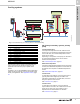
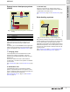

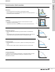
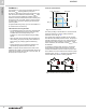
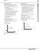
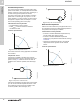
Table Of Contents
- 1. Product description
- 2. Product range
- 3. System applications
- 4. Functions
- Control modes: Quick overview
- Operating modes
- Control modes
- Additional control mode features
- Multipump modes
- Flow estimation accuracy
- Readings on the pump
- Performance overview
- Operating status and pump performance
- Warning and alarm
- Heat energy monitor
- Heat consumption accuracy
- Operating log
- Help and guidance
- Grundfos Eye
- Communication
- Grundfos GO Remote
- Wireless GENIair
- CIM modules
- Available CIM modules
- Grundfos Remote Management
- Digital inputs
- Relay outputs
- Analog input for an external sensor
- External setpoint function
- 5. Operating conditions
- 6. Construction
- 7. Installation
- 8. Operating the product
- 9. Curve conditions
- 10. Performance curves and technical data
- Conversion tables
- MAGNA3 32-60 F (N)
- MAGNA3 32-100 F (N)
- MAGNA3 32-120 F (N)
- MAGNA3 40-80 F (N)
- MAGNA3 40-120 F (N)
- MAGNA3 40-180 F (N)
- MAGNA3 50-80 F (N)
- MAGNA3 50-120 F (N)
- MAGNA3 50-150 F (N)
- MAGNA3 50-180 F (N)
- MAGNA3 65-120 F (N)
- MAGNA3 65-150 F (N)
- MAGNA3 D 65-150 F
- MAGNA3 80-100 F (N)
- MAGNA3 D 80-100 F
- MAGNA3 100-120 F (N)
- MAGNA3 D 100-120 F
- 11. Accessories
- 12. Product numbers
- 13. Grundfos Product Center

System applications
MAGNA3
3
12
4B. Primary/secondary system,
secondary pump
Secondary pumps are exposed to large variations in
flow and pressure losses due to load variations in the
system. For this reason, proportional pressure is the
recommended control mode.
If the pressure losses are below 5 mWc, the constant
pressure control mode is a good alternative.
If the pressure losses are unknown, you can choose
the AUTO
ADAPT
control mode, which will automatically
adjust the pump performance to the actual system
characteristic.
See Proportional pressure, page 19, Constant
pressure, page 19, and AUTO
ADAPT
, page 17.
5A. 'Primary only' system, primary pump
These pumps are exposed to large variations in flow
and pressure losses due to load variations in the
system. For this reason, proportional pressure is the
recommended control mode.
If the pressure losses are below 5 mWc, the
constant-pressure control mode is a good alternative.
If the pressure losses are unknown, you can choose
the AUTO
ADAPT
control mode, which will automatically
adjust the pump performance to the actual system
characteristic.
See Proportional pressure, page 19, Constant
pressure, page 19, and AUTO
ADAPT
, page 17.
6. Air handling unit
If the required flow in the coil is known, constant flow is
the preferred control mode. Here, the pump will adjust
to the needed pressure.
The actual heat supply is controlled by the motorised
valves as shown in fig. 11.
If the pressure loss in the coil is known, constant
pressure is a suitable control mode. This control mode
ensures that the pump is able to overcome the
pressure loss.
See Constant curve, page 21 and Constant pressure,
page 19.
7. Fan coil unit
Fan coil applications are characterised by variable flow
due to a varying number of coils in operation. The
more coils in operation the higher the pressure loss.
Therefore, proportional pressure is the optimum
control mode.
See Proportional pressure, page 19.
8. Underfloor/ceiling
In an underfloor/ceiling application the circuits are
individually balanced according to pressure loss. This
means that all circuits have the same pressure loss
even though they may differ in length.
Even if the flow varies, the pressure loss will remain
the same, and for this reason constant pressure is the
recommended control mode.
See Constant pressure, page 19.