
Submittal Sheet
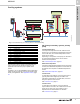
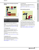
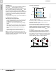
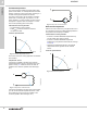
Table Of Contents
- 1. Product description
- 2. Product range
- 3. System applications
- 4. Functions
- Control modes: Quick overview
- Operating modes
- Control modes
- Additional control mode features
- Multipump modes
- Flow estimation accuracy
- Readings on the pump
- Performance overview
- Operating status and pump performance
- Warning and alarm
- Heat energy monitor
- Heat consumption accuracy
- Operating log
- Help and guidance
- Grundfos Eye
- Communication
- Grundfos GO Remote
- Wireless GENIair
- CIM modules
- Available CIM modules
- Grundfos Remote Management
- Digital inputs
- Relay outputs
- Analog input for an external sensor
- External setpoint function
- 5. Operating conditions
- 6. Construction
- 7. Installation
- 8. Operating the product
- 9. Curve conditions
- 10. Performance curves and technical data
- Conversion tables
- MAGNA3 32-60 F (N)
- MAGNA3 32-100 F (N)
- MAGNA3 32-120 F (N)
- MAGNA3 40-80 F (N)
- MAGNA3 40-120 F (N)
- MAGNA3 40-180 F (N)
- MAGNA3 50-80 F (N)
- MAGNA3 50-120 F (N)
- MAGNA3 50-150 F (N)
- MAGNA3 50-180 F (N)
- MAGNA3 65-120 F (N)
- MAGNA3 65-150 F (N)
- MAGNA3 D 65-150 F
- MAGNA3 80-100 F (N)
- MAGNA3 D 80-100 F
- MAGNA3 100-120 F (N)
- MAGNA3 D 100-120 F
- 11. Accessories
- 12. Product numbers
- 13. Grundfos Product Center

System applications
MAGNA3
3
11
Cooling systems
Fig. 11 Functional drawing of a cooling system in a commercial building
The following sections provide recommendations on
which control mode to choose according to your
application and where the pump is placed in the
system.
In addition, you can use MAGNA3's built-in application
wizard to help you identify which control mode is best
suited your application. See Application wizard, page
42.
4A. Primary/secondary system, primary
pump
Constant temperature
If the setpoint temperature from the chiller is known
and the aim is to maintain this temperature all the way
to the buffer tank, the constant-temperature control
mode can be chosen.
Depending on the position of the pump, the internal or
an external temperature sensor can be used to
measure the temperature.
See Constant temperature, page 20.
Differential temperature
If the design differential temperature across the chiller
is known, the differential temperature control mode can
be selected. This requires an additional temperature
sensor.
See Differential temperature, page 20.
Constant flow
In cases where the chiller is not varying, the pump is
typically started and stopped by the chiller. This
indicates a requirement for constant flow, hence this
being the optimum control mode.
See Constant curve, page 21.
Constant curve
In cases where the chiller is not varying and the
required delta-T is known, the constant-curve control
mode can be used. Here, the constant curve is
adjusted until the desired delta-T is obtained.
See Constant curve, page 21.
TM07 0358 1218
MM
M
T
T
1
2
4
5
78
6
AB
A
3
Pos. Description
1 Cooling tower
2 Cooling source
3 Chiller pump
4 Primary/secondary system
4A Primary pump
4B Secondary pump
5 "Primary only" system
5A Primary pump
6 Air handling unit
7 Fan coil unit
8 Underfloor/ceiling