
Submittal Sheet
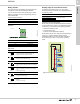
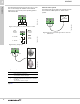
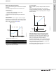
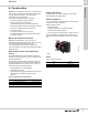
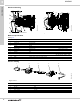
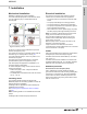
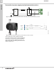
Table Of Contents
- 1. Product description
- 2. Product range
- 3. System applications
- 4. Functions
- Control modes: Quick overview
- Operating modes
- Control modes
- Additional control mode features
- Multipump modes
- Flow estimation accuracy
- Readings on the pump
- Performance overview
- Operating status and pump performance
- Warning and alarm
- Heat energy monitor
- Heat consumption accuracy
- Operating log
- Help and guidance
- Grundfos Eye
- Communication
- Grundfos GO Remote
- Wireless GENIair
- CIM modules
- Available CIM modules
- Grundfos Remote Management
- Digital inputs
- Relay outputs
- Analog input for an external sensor
- External setpoint function
- 5. Operating conditions
- 6. Construction
- 7. Installation
- 8. Operating the product
- 9. Curve conditions
- 10. Performance curves and technical data
- Conversion tables
- MAGNA3 32-60 F (N)
- MAGNA3 32-100 F (N)
- MAGNA3 32-120 F (N)
- MAGNA3 40-80 F (N)
- MAGNA3 40-120 F (N)
- MAGNA3 40-180 F (N)
- MAGNA3 50-80 F (N)
- MAGNA3 50-120 F (N)
- MAGNA3 50-150 F (N)
- MAGNA3 50-180 F (N)
- MAGNA3 65-120 F (N)
- MAGNA3 65-150 F (N)
- MAGNA3 D 65-150 F
- MAGNA3 80-100 F (N)
- MAGNA3 D 80-100 F
- MAGNA3 100-120 F (N)
- MAGNA3 D 100-120 F
- 11. Accessories
- 12. Product numbers
- 13. Grundfos Product Center

Functions
MAGNA3
4
32
The electrical signal for the input can be 0-10 V or 4-20
mA. You can change the selection of the electrical
signal (0-10 V or 4-20 mA) on the operating panel or
with Grundfos GO.
Fig. 41 Analog input for an external sensor or control
Fig. 42 Wiring, analog input
Fig. 43 Examples of external sensors
For further details, see External Grundfos sensors,
page 65.
External control system
The analog input can be used for an external signal for
the control from a BMS system or similar control
system.
Fig. 44 Example of an external signal for the control via
BMS or PLC
TM05 3221 1112TM05 3343 2313
TM06 7237 3416
Pos. Sensor type
1
Differential-pressure transmitter,
Grundfos type DPI V.2
1/2" connection and 4-20 mA signal.
2
Relative-pressure transmitter.
Combined temperature and pressure sensor, Grundfos
type RPI T2.
1/2" connection and 0-10 V signal.
signal
sensor
Vcc
24V
I
N
Max.
250 V AC
2 A AC1
Min.
5 V DC
20 mA
Max.
24 V DC
22 mA
0 - 10 V DC
4 - 20 mA
I
IN
24V
Vcc
Signal
Vcc
Signal
24V IN
Vcc Signal
1
2
TM05 2888 0612
24V
BMS
PLC