
Submittal Sheet
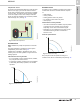
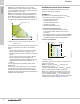
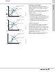
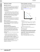
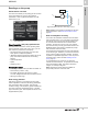
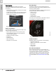
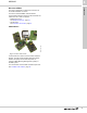
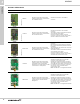
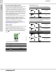
Table Of Contents
- 1. Product description
- 2. Product range
- 3. System applications
- 4. Functions
- Control modes: Quick overview
- Operating modes
- Control modes
- Additional control mode features
- Multipump modes
- Flow estimation accuracy
- Readings on the pump
- Performance overview
- Operating status and pump performance
- Warning and alarm
- Heat energy monitor
- Heat consumption accuracy
- Operating log
- Help and guidance
- Grundfos Eye
- Communication
- Grundfos GO Remote
- Wireless GENIair
- CIM modules
- Available CIM modules
- Grundfos Remote Management
- Digital inputs
- Relay outputs
- Analog input for an external sensor
- External setpoint function
- 5. Operating conditions
- 6. Construction
- 7. Installation
- 8. Operating the product
- 9. Curve conditions
- 10. Performance curves and technical data
- Conversion tables
- MAGNA3 32-60 F (N)
- MAGNA3 32-100 F (N)
- MAGNA3 32-120 F (N)
- MAGNA3 40-80 F (N)
- MAGNA3 40-120 F (N)
- MAGNA3 40-180 F (N)
- MAGNA3 50-80 F (N)
- MAGNA3 50-120 F (N)
- MAGNA3 50-150 F (N)
- MAGNA3 50-180 F (N)
- MAGNA3 65-120 F (N)
- MAGNA3 65-150 F (N)
- MAGNA3 D 65-150 F
- MAGNA3 80-100 F (N)
- MAGNA3 D 80-100 F
- MAGNA3 100-120 F (N)
- MAGNA3 D 100-120 F
- 11. Accessories
- 12. Product numbers
- 13. Grundfos Product Center

Functions
MAGNA3
4
30
Grundfos Remote Management
Grundfos Remote Management is an easy-to-install,
low-cost solution for wireless monitoring and
management of Grundfos products. GRM is based on
a centrally hosted database and a web server with
wireless data collection via GSM/GPRS modem. The
system only requires an internet connection, a web
browser, a GRM modem and an antenna as well as a
contract with Grundfos allowing you to monitor and
manage Grundfos pump systems.
You have wireless access to your account anywhere
and anytime you have an internet connection, for
example via a smartphone, tablet PC, laptop or
computer. Warnings and alarms can be sent by email
or SMS to your mobile phone or computer.
For information about the CIM communication
interface module and GSM antennas, see Grundfos
Remote Management, page 131.
Digital inputs
You can use the digital input for external control of start
or stop or forced maximum or minimum curve.
Note: If no external on and off switch is connected,
maintain the jumper between the Start/Stop (S/S) and
frame ( ) terminals. This connection is the factory
setting.
Fig. 38 Digital input in control box
External start or stop
You can start and stop the pump via the digital input.
External forced maximum or minimum curve
You can force the pump to operate on the maximum or
minimum curve via the digital input.
TM05 3343 1212
Contact symbol Function
M
A
Maximum curve
M
I
Minimum curve
S/S Start/Stop
Frame connection
NC N0 C
S/S
M
I
M
A
Start/Stop
Normal duty
Stop
Maximum curve
Normal duty
Maximum curve
Minimum curve
Normal duty
Minimum curve
S/S
Q
H
S/S
Q
H
M
A
Q
H
M
A
Q
H
Q
H
Q
H