
Submittal Sheet
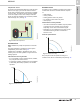
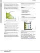
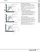
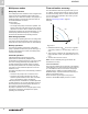
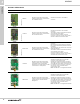
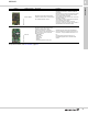
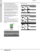
Table Of Contents
- 1. Product description
- 2. Product range
- 3. System applications
- 4. Functions
- Control modes: Quick overview
- Operating modes
- Control modes
- Additional control mode features
- Multipump modes
- Flow estimation accuracy
- Readings on the pump
- Performance overview
- Operating status and pump performance
- Warning and alarm
- Heat energy monitor
- Heat consumption accuracy
- Operating log
- Help and guidance
- Grundfos Eye
- Communication
- Grundfos GO Remote
- Wireless GENIair
- CIM modules
- Available CIM modules
- Grundfos Remote Management
- Digital inputs
- Relay outputs
- Analog input for an external sensor
- External setpoint function
- 5. Operating conditions
- 6. Construction
- 7. Installation
- 8. Operating the product
- 9. Curve conditions
- 10. Performance curves and technical data
- Conversion tables
- MAGNA3 32-60 F (N)
- MAGNA3 32-100 F (N)
- MAGNA3 32-120 F (N)
- MAGNA3 40-80 F (N)
- MAGNA3 40-120 F (N)
- MAGNA3 40-180 F (N)
- MAGNA3 50-80 F (N)
- MAGNA3 50-120 F (N)
- MAGNA3 50-150 F (N)
- MAGNA3 50-180 F (N)
- MAGNA3 65-120 F (N)
- MAGNA3 65-150 F (N)
- MAGNA3 D 65-150 F
- MAGNA3 80-100 F (N)
- MAGNA3 D 80-100 F
- MAGNA3 100-120 F (N)
- MAGNA3 D 100-120 F
- 11. Accessories
- 12. Product numbers
- 13. Grundfos Product Center

Functions
MAGNA3
4
22
Depending on the pump model, you can set the
desired speed in % of the maximum speed. The span
of control depends on the minimum speed, power and
pressure limitation of the pump.
Note: If the pump speed is set in the range between
minimum and maximum, the power and pressure are
limited when the pump is running on the maximum
curve. This means that the maximum performance can
be achieved at a speed lower than 100 %. See fig. 27.
Fig. 27 Power and pressure limitations influencing the
maximum curve
You can also set the pump to operate according to the
maximum or minimum curve, like an uncontrolled
pump:
• You can use the maximum curve mode in periods
where a maximum flow rate is required. This
operating mode is for instance suitable for hot-water
priority.
• You can use the minimum curve mode in periods
where a minimum flow rate is required. This
operating mode is for instance suitable for manual
night setback if automatic night setback is not
desired.
You can select these two operating modes via the
digital inputs.
In the control mode constant curve, you can obtain a
constant flow by choosing a setpoint at 100 % and
choosing the desired value for the flow rate with the
FLOW
LIMIT
function. Take the accuracy of the flow rate
estimation into consideration.
Additional control mode features
MAGNA3 offers additional features for the control
modes to meet specific demands.
FLOW
LIMIT
The feature is an integrated part of the FLOW
ADAPT
control mode, but is also advantageous in:
• proportional-pressure mode
• constant-pressure mode
• constant-temperature mode
• constant-curve mode
• differential-temperature mode.
Characteristics and key benefits
• A control mode feature that, when activated,
ensures that the rated maximum flow is never
exceeded.
• By enabling FLOW
LIMIT
in systems where MAGNA3
has full authority, the rated flow is never exceeded,
thus eliminating the need for throttling valves.
Technical specifications
Fig. 28 FLOW
LIMIT
The setting range for the FLOW
LIMIT
is 25 to 90 % of
the Q
max
of the pump.
Note: Do not set the FLOW
LIMIT
lower than the
dimensioned duty point.
In the flow rate range between 0 and Q
limit
, the pump
will run according to the selected control mode.
When Q
limit
is reached, the FLOW
LIMIT
function will
reduce the pump speed to ensure that the flow rate
never exceeds the FLOW
LIMIT
set, no matter if the
system requires a higher flow rate due to an increased
resistance in the system. See figs 29, 30 and 31.
TM05 4266 2212
H
Q
Min.
30%
50%
70%
90%
Limited max. curve
Speed setting from 0 to 100 %
TM05 2445 1312
H
Q
Q
max
Q
limit
90 %
Q
max
25 %
Setting range