
Submittal Sheet
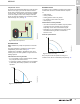
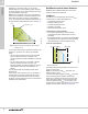
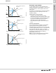
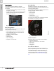

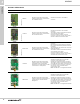
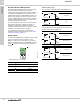
Table Of Contents
- 1. Product description
- 2. Product range
- 3. System applications
- 4. Functions
- Control modes: Quick overview
- Operating modes
- Control modes
- Additional control mode features
- Multipump modes
- Flow estimation accuracy
- Readings on the pump
- Performance overview
- Operating status and pump performance
- Warning and alarm
- Heat energy monitor
- Heat consumption accuracy
- Operating log
- Help and guidance
- Grundfos Eye
- Communication
- Grundfos GO Remote
- Wireless GENIair
- CIM modules
- Available CIM modules
- Grundfos Remote Management
- Digital inputs
- Relay outputs
- Analog input for an external sensor
- External setpoint function
- 5. Operating conditions
- 6. Construction
- 7. Installation
- 8. Operating the product
- 9. Curve conditions
- 10. Performance curves and technical data
- Conversion tables
- MAGNA3 32-60 F (N)
- MAGNA3 32-100 F (N)
- MAGNA3 32-120 F (N)
- MAGNA3 40-80 F (N)
- MAGNA3 40-120 F (N)
- MAGNA3 40-180 F (N)
- MAGNA3 50-80 F (N)
- MAGNA3 50-120 F (N)
- MAGNA3 50-150 F (N)
- MAGNA3 50-180 F (N)
- MAGNA3 65-120 F (N)
- MAGNA3 65-150 F (N)
- MAGNA3 D 65-150 F
- MAGNA3 80-100 F (N)
- MAGNA3 D 80-100 F
- MAGNA3 100-120 F (N)
- MAGNA3 D 100-120 F
- 11. Accessories
- 12. Product numbers
- 13. Grundfos Product Center

Functions
MAGNA3
4
25
Readings on the pump
Performance overview
The home menu allows you to quickly gain an overview
of the main settings of up to four user-defined
parameters or view a graphical illustration of a QH
performance curve.
Fig. 33 Example of Home menu with overview of settings
and performance
Operating status and pump performance
The status menu shows the current operating mode
and the selected control mode, if any. Here, you can
also review the performance of the pump:
• QH graph showing current duty point, flow rate,
head, power and liquid temperature.
• "Resulting setpoint" showing the setpoint set on the
pump, the external influence and the resulting
setpoint.
• Liquid temperature.
• Speed.
• Operating hours.
Warning and alarm
The Warning and alarm menu provides information on:
• actual warning or alarm, if any
• information about when the warning or alarm
occurred, disappeared and about corrective actions
• Warning and alarm logs.
Heat energy monitor
Heat energy monitor is a monitoring function which
makes it possible to track the heat energy distribution
and consumption within a system. This prevents
excessive energy costs caused by system imbalances.
The pump requires a temperature sensor in the flow
pipe or the return pipe. This temperature sensor is not
supplied with the pump.
Fig. 34 MAGNA3 with built-in heat energy monitor
Note: MAGNA3 incorporates a calculator for flow and
media temperature, see External Grundfos sensors,
page 65.
Heat consumption accuracy
The built-in flow estimation needed for the calculation
has a typical accuracy of ± 5 % of Qmax. The less flow
through the pump, the less accurate the reading will
be. In worst case scenarios such as closed valve
operation, the accuracy can be up to 10 % of Qmax.
The actual accuracy in a duty point will be shown in the
MAGNA3 display (this feature is available for pumps
with production code from 1838).
The temperature measurement accuracy also depends
on the sensor type. Therefore, you cannot use the heat
energy value for billing purposes. However, the value
is perfect for optimisation purposes in order to prevent
excessive energy costs. See also Readings on the
pump, page 25.
To counterbalance any inaccuracy on either the
internal and external sensor, it is possible to manually
enter a temperature offset. The offset is entered in
integers, for example 2 degrees.
Note: Temperature sensor offset is available for
pumps with production code from 1838.
undef-010_HOME_us
TM05 5367 3612
t
kWh
F
t
R