
Submittal Sheet
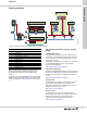
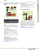

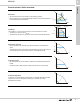
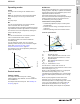
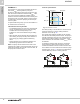
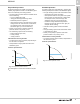
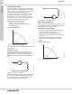
Table Of Contents
- 1. Product description
- 2. Product range
- 3. System applications
- 4. Functions
- Control modes: Quick overview
- Operating modes
- Control modes
- Additional control mode features
- Multipump modes
- Flow estimation accuracy
- Readings on the pump
- Performance overview
- Operating status and pump performance
- Warning and alarm
- Heat energy monitor
- Heat consumption accuracy
- Operating log
- Help and guidance
- Grundfos Eye
- Communication
- Grundfos GO Remote
- Wireless GENIair
- CIM modules
- Available CIM modules
- Grundfos Remote Management
- Digital inputs
- Relay outputs
- Analog input for an external sensor
- External setpoint function
- 5. Operating conditions
- 6. Construction
- 7. Installation
- 8. Operating the product
- 9. Curve conditions
- 10. Performance curves and technical data
- Conversion tables
- MAGNA3 32-60 F (N)
- MAGNA3 32-100 F (N)
- MAGNA3 32-120 F (N)
- MAGNA3 40-80 F (N)
- MAGNA3 40-120 F (N)
- MAGNA3 40-180 F (N)
- MAGNA3 50-80 F (N)
- MAGNA3 50-120 F (N)
- MAGNA3 50-150 F (N)
- MAGNA3 50-180 F (N)
- MAGNA3 65-120 F (N)
- MAGNA3 65-150 F (N)
- MAGNA3 D 65-150 F
- MAGNA3 80-100 F (N)
- MAGNA3 D 80-100 F
- MAGNA3 100-120 F (N)
- MAGNA3 D 100-120 F
- 11. Accessories
- 12. Product numbers
- 13. Grundfos Product Center

Functions
MAGNA3
4
20
Constant temperature
This control mode is suitable in systems with a fixed
system characteristic, for example domestic hot-water
systems, where the control of the pump according to a
constant return-pipe temperature is relevant.
The pump is from factory set to operate in a heating
system with a controller gain, Kp, equal to 1. If the
pump operates in a cooling system, the gain must be
changed to a negative value, for example -1. This is
done via the operating panel of the pump.
Characteristics and key benefits
• The temperature is kept constant.
•FLOW
LIMIT
is used to control the maximum
circulation flow rate.
Technical specifications
Fig. 20 Constant-temperature control
The inverse control for cooling application is available
from model B.
Temperature sensor
If the pump is installed in the flow pipe, install an
external temperature sensor in the return pipe of the
system. See fig. 21. Install the sensor as close as
possible to the consumer (radiator, heat exchanger,
etc.).
Fig. 21 Pump with an external sensor
If the pump is installed in the return pipe of the system,
you can use the internal temperature sensor. In this
case, install the pump as close as possible to the
consumer (radiator, heat exchanger, etc.).
Fig. 22 Pump with an internal sensor
Differential temperature
Select this control mode if the pump performance is to
be controlled according to a differential temperature in
the system where the pump is installed.
Characteristics and key benefits
• Ensures a constant differential temperature drop
across heating and cooling systems.
• Ensures a constant differential temperature
between the pump and the external sensor, see figs
23 and 24.
• Requires two temperature sensors, the internal
temperature sensor together with an external
sensor.
Technical specifications
Fig. 23 Differential temperature
TM05 2451 5111 TM05 2615 0312
H
Q
t
F
t
R
TM05 2616 0312TM05 2451 5111
t
F
t
R
H
Q
Δt