GRUNDFOS DATA BOOKLET MAGNA3 From Model D Circulator pumps 50/60 Hz
MAGNA3 Table of contents 1. Product description 2. 3. 4. 5. 6. 7. 8. 9.
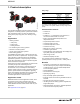
1 MAGNA3 Product description 1. Product description Duty range Data Maximum flow rate TM05 8894 2813 Maximum head Maximum system pressure Liquid temperature The Grundfos MAGNA3 model D circulator pumps are designed for circulating liquids in systems with variable flow requirements where you want to optimize the setting of the pump duty point, thus reducing energy costs.
1 MAGNA3 Product description Type key Code Example MAGNA3 (D) 80 -120 (F) (N) 360 Type range MAGNA3 D Single-head pump Twin-head pump Nominal diameter (DN) of inlet and outlet ports [mm] Maximum head [dm] F Pipe connection Flange N Pump housing material Cast iron Stainless steel Port-to-port length [mm] This data booklet covers MAGNA3 from model D. The model version is stated on the nameplate. See fig. 1. The twin-head pump housing has a flap valve on the outlet side.
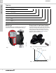
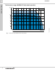
1 MAGNA3 H [m] H [ft] MAGNA3 60 40-180 50 40 32-120 10 9 Product description Performance range, MAGNA3 50-150 5 0-1 40-120 65-120 65-150 80 50-180 100-120 30 8 32-100 7 6 80-100 20 50-120 5 15 4 50-80 40-80 32-60 12 3 10 TM05 7654 2818 8 2 6 10 15 3 Fig.
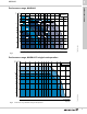
1 MAGNA3 Product description Performance range, MAGNA3 D twin-head operation H [m] H [ft] MAGNA3 D 50 65-150 40 100-120 10 9 8 30 80-100 25 7 6 20 5 15 10 10 15 20 30 40 60 80 100 150 200 300 400 600 Q [US GPM] 3 Fig.
2 MAGNA3 Port-to-port length [in. (mm)] Cast iron Product range 2.
2 MAGNA3 Communication • AUTOADAPT (factory setting) which is suitable for most installations. • FLOWADAPT in systems where flow limitation is required. • Proportional-pressure control in systems with considerable pressure losses in relation to large flow variations. • Constant-pressure control in systems with insignificant pressure losses in relation to large flow variations. • Constant-temperature control in systems with a fixed system characteristic, for example domestic hot-water systems.
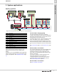
3 MAGNA3 System applications 3. System applications Heating systems 1 2 3 A B C 4 5 6 7 T T D M M M M M E M TM07 0360 1218 8 Fig. 10 Functional drawing of a heating system in a commercial building Pos.
3 MAGNA3 System applications 3. Air handling unit 7. Underfloor/ceiling Constant flow In these systems the flow will vary depending on how many rooms are in operation. However, since the distance is short between the pump and manifold, to which the pipes are connected, there is no variation in pressure losses. Because of this the constant-pressure control mode is the optimum choice. See Constant pressure, page 19.
3 MAGNA3 System applications Cooling systems 6 1 3 7 8 T 4 T A B 2 M M M TM07 0358 1218 5 A Fig. 11 Functional drawing of a cooling system in a commercial building 1 Cooling tower 4A.
3 MAGNA3 System applications 4B. Primary/secondary system, secondary pump Secondary pumps are exposed to large variations in flow and pressure losses due to load variations in the system. For this reason, proportional pressure is the recommended control mode. If the pressure losses are below 5 mWc, the constant pressure control mode is a good alternative.
3 MAGNA3 1 2 3. Ground loop System applications Ground source heat pump systems (GSHP) Since the ground loop is a closed system with no variations in flow, the most suitable control modes are constant flow and constant curve. See Constant flow, page 21 and Constant curve, page 21. T Solar-heating systems T Fig. 12 Ground source heat pump system in a commercial building Pos.
4 MAGNA3 Functions 4.
4 MAGNA3 Functions Control modes: Quick overview H AUTOADAPT • We recommend this control mode for most heating systems. • During operation, the pump automatically makes the necessary adjustment to the actual system characteristic. Hset1 A1 Hauto_min A3 A2 Hset2 Q H 25 % Q max 90 % Q max FLOWADAPT The FLOWADAPT control mode combines a control mode and a function: • The pump is running in AUTOADAPT. • The delivered flow from the pump will never exceed a selected FLOWLIMIT.
4 MAGNA3 Functions H Δt Differential temperature • Ensures a constant differential temperature drop across heating and cooling systems. • The pump will maintain a constant differential temperature between the pump and the external sensor. Q H Constant flow Note: Available for pumps with production code from 1838. • The pump maintains a constant flow in the system independently of the head. • It is not possible to use an external sensor, instead, the pump uses its internal sensor.
4 MAGNA3 Operating modes Functions AUTOADAPT We recommend the AUTOADAPT control mode for most heating systems, especially in systems with relatively large pressure losses in the distribution pipes, and in replacement situations where the proportional-pressure duty point is unknown. This control mode has been developed specifically for heating systems and we do not recommend it for air-conditioning and cooling systems. Normal The pump runs according to the selected control mode.
4 MAGNA3 The FLOWADAPT control mode combines AUTOADAPT and FLOWLIMIT, meaning that the pump runs AUTOADAPT while at the same time ensuring that the flow rate never exceeds the entered FLOWLIMIT value. This control mode is suitable for systems where a maximum flow limit is desired and where a steady flow through the boiler in a boiler system is required. Here, no extra energy is used for pumping too much liquid into the system.
4 Proportional pressure Constant pressure Proportional pressure is suitable in systems with relatively large pressure losses in the distribution pipes and in air-conditioning and cooling systems: • Two-pipe heating systems with thermostatic valves and the following: – very long distribution pipes – strongly throttled pipe balancing valves – differential-pressure regulators – large pressure losses in the parts of the system through which the entire amount of water flows, for example a boiler, heat exchang
4 MAGNA3 This control mode is suitable in systems with a fixed system characteristic, for example domestic hot-water systems, where the control of the pump according to a constant return-pipe temperature is relevant. The pump is from factory set to operate in a heating system with a controller gain, Kp, equal to 1. If the pump operates in a cooling system, the gain must be changed to a negative value, for example -1. This is done via the operating panel of the pump.
4 Temperature sensor Constant curve To measure the temperature difference of the flow pipe and the return pipe, you must use both the internal sensor and an external sensor. If the pump is installed in the flow pipe, the external sensor must be installed in the return pipe and vice versa. Always install the sensor as close as possible to the consumer (radiator, heat exchanger, etc.). See fig. 24.
4 MAGNA3 H Limited max. curve % % 30 90% n. Q Speed setting from 0 to 100 % TM05 4266 2212 % Mi Fig. 27 Power and pressure limitations influencing the maximum curve You can also set the pump to operate according to the maximum or minimum curve, like an uncontrolled pump: • You can use the maximum curve mode in periods where a maximum flow rate is required. This operating mode is for instance suitable for hot-water priority.
4 MAGNA3 Hset FLOWLIMIT duty point Hset 2 Q MJNJU Fig. 29 Proportional-pressure control with FLOWLIMIT Hset Normal constant-pressure duty point Q MJNJU Fig. 30 Constant-pressure control with FLOWLIMIT H A night setback system is often integrated into a building management system (BMS), or as part of an equivalent electronic control system, which has a built-in timer. The feature is not beneficial in rooms with underfloor heating because of the regulating inertia of the underfloor heating.
4 MAGNA3 Multipump function The multipump function enables control of single-head pumps connected in parallel and twin-head pumps without the use of external controllers. The pumps in a multipump system communicate with each other via the wireless GENIair connection. Pump system: • Twin-head pump. • Two single-head pumps connected in parallel. The pumps must be of equal size and type. Each pump requires a non-return valve in series with the pump. A multipump system is set via a selected pump, i.e.
4 MAGNA3 Functions Readings on the pump kWh Performance overview tF tR TM05 5367 3612 The home menu allows you to quickly gain an overview of the main settings of up to four user-defined parameters or view a graphical illustration of a QH performance curve. undef-010_HOME_us Fig. 34 MAGNA3 with built-in heat energy monitor Fig.
4 MAGNA3 Functions Operating log Grundfos Eye The Operating log is the perfect tool for pump optimization, replacement and fault finding as it offers the following: • All duty points and operating conditions are tracked and stored in the pump. • The 3D work log and duty curve (over time) provide instant overviews of historical pump performance and operating conditions. Grundfos Eye at the top of the operating panel is a pump status indicator light providing information about the pump operating status.
4 MAGNA3 Functions Wireless GENIair The pump is designed for multipump connection via the wireless GENIair connection. The built-in wireless GENIair module enables communication between pumps and with Grundfos GO without the use of add-on modules: • Multipump function. See Multipump function, page 24. • Grundfos GO. See Grundfos GO Remote, page 64. TM05 3811 1612 CIM modules Fig. 37 Grundfos CIM modules A CIM module is an add-on Communication Interface Module.
4 MAGNA3 Functions Available CIM modules Module Fieldbus protocol Description Functions GENIbus CIM 050 is a Grundfos communication interface module used for communication with a GENIbus network. CIM 050 has terminals for the GENIbus connection. CIM 100 is a Grundfos communication interface module used for communication with a LonWorks network. CIM 100 has terminals for the LonWorks connection. Two LEDs are used to indicate the actual status of the CIM 100 communication.
4 Module Fieldbus protocol Description Functions BACnet MS/TP CIM 300 is a Grundfos communication interface module used for communication with a BACnet MS/TP network. CIM 300 has terminals for the BACnet MS/TP connection. DIP switches are used to set transmission speed and line termination and to select the custom Device Object Instance Number. Two hexadecimal rotary switches are used to set the BACnet address. Two LEDs are used to indicate the actual status of the CIM 300 communication.
4 MAGNA3 Functions Grundfos Remote Management External start or stop Grundfos Remote Management is an easy-to-install, low-cost solution for wireless monitoring and management of Grundfos products. GRM is based on a centrally hosted database and a web server with wireless data collection via GSM/GPRS modem. The system only requires an internet connection, a web browser, a GRM modem and an antenna as well as a contract with Grundfos allowing you to monitor and manage Grundfos pump systems.
4 Relay outputs Analog input for an external sensor The pump has two signal relays with a potential-free changeover contact for external fault indication. You can set the function of the signal relay to Alarm, Ready or Operation on the pump operating panel or with Grundfos GO.
4 MAGNA3 Functions The electrical signal for the input can be 0-10 V or 4-20 mA. You can change the selection of the electrical signal (0-10 V or 4-20 mA) on the operating panel or with Grundfos GO. External control system The analog input can be used for an external signal for the control from a BMS system or similar control system. BMS signal sensor PLC 24V TM05 2888 0612 Vcc TM05 3221 1112 IN 24V Fig. 41 Analog input for an external sensor or control Max.
4 External setpoint function Linear with Stop You can use the analog input to influence the setpoint externally. The external setpoint function can be used in two different ways: • Linear with Min. • Linear with Stop (available for pumps with production code from 1838) In both modes the input signal range is influenced linearly. Note: Available for pumps with production code from 1838. Here, if the input signal is below 10 %, the pump changes to operating mode "Stop".
5 MAGNA3 Operating conditions 5.
5 Minimum inlet pressure Closed valve operation The following relative minimum pressure must be available at the pump inlet during operation to avoid cavitation noise and damage to the pump bearings. The values in the table below apply to single-head pumps and twin-head pumps in single-head operation. MAGNA3 pumps can operate at any speed against a closed valve for several days without damage to the pump.
5 MAGNA3 Operating conditions Electrical data Pump type MAGNA3 (D) Enclosure class Type 2 Insulation class F. Supply voltage Three digital inputs Analog input Two relay outputs Bus input Leakage current EMC Cos φ Consumption when the pump is stopped * 1 x 115-230 V ± 10 %, 60 Hz*, PE. M20 cable gland (supplied with the pump). External potential-free contact. Contact load: 5 V, 10 mA. Screened cable. M16 cable gland (not supplied with the pump). Loop resistance: Maximum 130 Ω.
6 MAGNA3 MAGNA3 is of the canned-rotor type, i.e. the pump and motor form an integral unit without shaft seal and with only two gaskets for sealing. The bearings are lubricated by the pumped liquid.
6 MAGNA3 Construction Sectional drawing 4 3 2 5 6 1 8 Fig. 49 Terminal-connected version TM07 1970 2518 TM05 2319 0312 7 Fig. 50 Wire-to-wire-connected version Material specification See fig. 49. Pos. Component Material 1 Outer bearing ring Aluminium oxide 2 Control box Polycarbonate Stator housing Aluminium 3 Grade O-rings EPDM 4 Thrust bearing Aluminium oxide/carbon 5 Bearing plate Stainless steel AISI 304 (EN 1.4301) 6 Neck ring Stainless steel AISI 304 (EN 1.
7 MAGNA3 Mechanical installation Electrical installation MAGNA3 is designed for indoor installation. You must install the pump with horizontal motor shaft. You can install the pump in horizontal as well as vertical pipes. The electrical connection and protection must be carried out in accordance with local regulations. • The pump must be connected to an external main switch. • The pump must always be correctly grounded. • The pump requires no external motor protection.
7 MAGNA3 Installation Connection to power supply, terminal-connected versions L L TM03 2397 3216 N N GFCI Fig. 53 Example of a terminal-connected motor with main switch, backup fuse and additional protection TM071415 1618 GFCI Fig. 54 Example of electrical connections for models with wire-to-wire connections Use a suitable type of GFCI capable of handling ground fault currents with a DC content (pulsating DC).
7 Installation MAGNA3 Analog input IN 24V Signal Vcc Sensor M A M I S/S Relay 1 Relay 2 Power NC NO C NC NO C Operation Alarm L N Digital input Start/stop On/off timer TM07 0364 1518 Use C and NC for fault signals as this enables serial connections of more relays and detection of signal cable defects. GFCI L N Fig.
8 MAGNA3 Operating the product 8. Operating the product MAGNA3 can be operated and monitored via the operating panel on the pump and via the Grundfos GO Remote app. The MAGNA3 pump range allows you to set the pump directly on the user-friendly, 4" TFT operating panel with self-explanatory push-buttons made of high-quality silicone for precise navigation. The operating panel gives quick and easy access to pump and performance data on site.
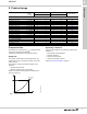
9 MAGNA3 Curve conditions 9. Curve conditions Performance curves The guidelines below apply to the performance curves on pages 45 to 62: • Test liquid: airless water. • The curves apply to a density of ρ = 983.2 kg/m3 and a liquid temperature of 140 °F (60 °C). • All curves show average values. If a specific minimum performance is required, individual measurements must be made. • The curves apply to a kinematic viscosity of μ = 0.474 mm2/s (0.474 cSt). • Reference supply voltage: 1 x 230 V, 50 Hz.
9 MAGNA3 Curve conditions Markings and approvals The following marks are available after positive testing of MAGNA3: Mark Description Intertek - ETL Listed for USA and Canada Conforms to ANSI/UL Std. 778 Motor Operated Water Pumps Certified to CAN/CSA C22.2 No. 108 Liquid Pumps USA and Canada Applies to pumps with stainless steel pump housing (flange).
Performance curves and technical data 10 Performance curves and technical data MAGNA3 10.
10 Performance curves and technical data MAGNA3 Performance curves and technical data MAGNA3 32-60 F (N) 1 x 115, 230 V, 60 Hz Proportional pressure Constant pressure H [ft] AUTO ADAPT 0-10 volts* H [ft] H [ft] 22 22 20 20 20 10 V 18 18 18 9V 16 16 16 14 14 14 12 12 12 10 10 10 8 8 8 6 6 6 4 4 4 2 2 2 0 0 22 0 4 8 12 16 20 24 28 32 36 40 Q [US gpm] P1 [W] 110 100 90 80 70 60 50 40 30 20 10 0 Speed 0 4 8 12 16 20 24 28 32 36 40 Q [US gp
Performance curves and technical data MAGNA3 32-100 F (N) 1 x 115, 230 V, 60 Hz Proportional pressure H [ft] Constant pressure AUTO ADAPT 0-10 volts* H [ft] H [ft] 36 36 32 32 32 28 28 28 24 24 24 8V 20 20 20 7V 16 16 16 6V 12 12 12 5V 8 8 8 4V 4 4 4 36 0 0 5 10 15 20 25 30 35 40 45 50 Q [US gpm] P1 [W] 180 160 140 120 100 80 60 40 20 0 Speed 10 Performance curves and technical data MAGNA3 0 0 5 10 15 20 25 30 35 40 45 50 Q [US gpm] 0 10
10 Performance curves and technical data MAGNA3 Performance curves and technical data MAGNA3 32-120 F (N) 1 x 115, 230 V, 60 Hz Proportional pressure Constant pressure 0-10 volts* H [ft] 48 H [ft] 48 H [ft] 48 44 44 44 40 40 40 36 36 36 32 32 32 28 28 28 24 24 24 20 20 20 16 16 16 12 12 12 8 8 8 4 4 4 0 0 5 0 10 15 20 25 30 35 40 45 50 55 60 Q [US GPM] P1 [W] 200 P1 [W] 200 160 160 120 120 80 80 40 40 0 0 Speed P1 [W] 115 V I1 [A] 115 V 0 0 1
Performance curves and technical data MAGNA3 40-80 F (N) 1 x 115, 230 V, 60 Hz Proportional pressure Constant pressure 0-10 volts* H [ft] 30 H [ft] 30 28 28 28 26 26 26 24 24 24 22 22 22 20 20 20 18 18 18 16 16 16 14 14 14 12 12 12 10 10 10 5V 8 8 8 4V 6 6 6 4 4 4 3V 2V H [ft] 30 AUTO ADAPT 2 0 10 20 30 40 50 60 70 80 0 90 Q [US gpm] P1 [W] 280 P1 [W] 280 240 240 200 200 160 160 120 120 80 80 40 40 0 0 Speed P1 [W] 115 V I1 [A]
10 Performance curves and technical data MAGNA3 Performance curves and technical data MAGNA3 40-120 F (N) 1 x 115, 230 V, 60 Hz Proportional pressure Constant pressure H [ft] AUTO ADAPT 44 0-10 volts* H [ft] H [ft] 44 44 40 40 40 36 36 36 32 32 32 28 28 28 8V 24 24 24 7V 20 20 20 16 16 16 12 12 12 8 8 8 4 4 4 0 0 10 20 30 40 50 60 70 80 90 100 110 120 Q [US gpm] 0 0 P1 [W] P1 [W] 400 400 300 300 200 200 100 100 0 0 Speed P1 [W] 115 V I1 [A] 1
Performance curves and technical data MAGNA3 40-180 F (N) 1 x 115, 230 V, 60 Hz Proportional pressure H [ft] Constant pressure AUTO ADAPT 0-10 volts* H [ft] H [ft] 65 65 60 60 60 55 55 55 50 50 50 45 45 45 40 40 40 35 35 35 30 30 30 25 25 25 20 20 20 15 15 15 10 10 10 5 5 5 0 0 65 0 20 40 60 80 100 120 140 Q [US gpm] 0 P1 [W] 600 P1 [W] 600 500 500 400 400 300 300 200 200 100 100 0 0 P1 [W] 115 V Speed 10 Performance curves and techni
10 Performance curves and technical data MAGNA3 Performance curves and technical data MAGNA3 50-80 F (N) 1 x 115, 230 V, 60 Hz Proportional pressure H [ft] 30 Constant pressure 0-10 volts* H [ft] 30 H [ft] 30 28 28 28 26 26 26 24 24 24 22 22 22 20 20 20 18 18 18 16 16 16 14 14 14 12 12 12 10 10 10 5V 8 8 8 4V 6 6 6 4 4 4 3V 2V 2 2 2 0 AUTO ADAPT 0 20 40 60 80 100 120 140 Q [US gpm] 0 P1 [W] 350 P1 [W] 350 300 300 250 250 200 200 150
Performance curves and technical data MAGNA3 50-120 F (N) 1 x 115, 230 V, 60 Hz Proportional pressure Constant pressure H [ft] AUTO ADAPT 44 0-10 volts* H [ft] H [ft] 44 44 40 40 40 36 36 36 32 32 32 28 28 28 24 24 24 20 20 20 16 16 16 12 12 12 8 8 8 4 4 4 0 0 20 40 60 80 100 120 140 10 Performance curves and technical data MAGNA3 160 0 Q [US GPM] P1 [W] P1 [W] 500 500 400 400 300 300 200 200 100 100 0 0 0 20 40 60 Speed P1 [W] 115
10 Performance curves and technical data MAGNA3 Performance curves and technical data MAGNA3 50-150 F (N) 1 x 115, 230 V, 60 Hz Proportional pressure Constant pressure 0-10 volts* H [ft] 56 H [ft] 56 52 52 52 48 48 48 44 44 44 40 40 40 36 36 36 32 32 32 28 28 28 24 24 24 20 20 20 6V 16 16 16 5V 12 12 12 4V 8 8 8 4 4 4 3V 2V H [ft] 56 AUTO ADAPT 0 0 20 40 60 80 0 100 120 140 160 180 Q [US gpm] P1 [W] 700 P1 [W] 700 600 600 500 500 400 400
Performance curves and technical data MAGNA3 50-180 F (N) 1 x 115, 230 V, 60 Hz Proportional pressure H [ft] Constant pressure 0-10 volts* H [ft] H [ft] 60 60 55 55 55 50 50 50 45 45 45 40 40 40 35 35 35 30 30 30 25 25 25 20 20 20 15 15 15 10 10 10 5 5 5 AUTO ADAPT 60 0 0 20 40 60 80 10 Performance curves and technical data MAGNA3 0 100 120 140 160 180 200 Q [US GPM] 0 P1 [W] 800 P1 [W] 800 600 600 400 400 200 200 0 0 20 40 60 Speed P1 [
10 Performance curves and technical data MAGNA3 Performance curves and technical data MAGNA3 65-120 F (N) 1 x 115, 230 V, 60 Hz Proportional pressure Constant pressure 0-10 volts* 44 H [ft] 44 40 40 40 10 V 36 36 36 9V 32 32 32 28 28 28 24 24 24 20 20 20 16 16 16 12 12 12 8 8 8 4 4 4 H [ft] H [ft] 44 0 AUTO ADAPT 0 0 20 40 60 80 100 120 140 160 180 200 220 Q [US gpm] P1 [W] 800 P1 [W] 800 700 700 600 600 500 500 400 400 300 300 200 200 100 100
Performance curves and technical data MAGNA3 65-150 F (N) 1 x 230 V, 60 Hz Proportional pressure Constant pressure 0-10 volts* H [ft] 56 H [ft] 56 52 52 52 48 48 48 44 44 44 40 40 40 36 36 36 32 32 32 28 28 28 24 24 24 20 20 20 16 16 16 5V 12 12 12 4V 8 8 8 4 4 4 3V 2V H [ft] 56 0 AUTO ADAPT 0 40 80 120 160 200 0 280 Q [US gpm] 0 240 P1 [W] 1,400 P1 [W] 1,400 1,200 1,200 1,000 1,000 800 800 600 600 400 400 200 200 0 0 40 P1 [W] 23
10 Performance curves and technical data MAGNA3 Performance curves and technical data MAGNA3 D 65-150 F 1 x 230 V, 60 Hz Proportional pressure H [ft] 56 Constant pressure 0-10 volt* H [ft] H [ft] 56 56 52 52 48 48 44 44 40 40 40 36 36 36 32 32 32 28 28 28 24 24 24 20 AUTO ADAPT 52 48 44 10 V 9V 8V 7V 6V 20 20 16 16 16 5V 12 12 12 4V 8 8 8 4 4 4 3V 2V 0 0 40 80 120 160 200 240 280 Q [US gpm] 0 0 50 100 150 200 250 300 350 Q [US gpm] 0
Performance curves and technical data MAGNA3 80-100 F (N) 1 x 230 V, 60 Hz Proportional pressure H [ft] 38 36 34 32 30 28 26 24 22 20 18 16 14 12 10 8 6 4 2 0 Constant pressure H [ft] 38 36 34 32 30 28 26 24 22 20 18 16 14 12 10 8 6 4 2 0 280 Q [US gpm] 0 AUTO ADAPT 0 40 80 120 160 200 10 Performance curves and technical data MAGNA3 240 P1 [W] 1,100 1,000 900 800 700 600 500 400 300 200 100 0 40 80 120 160 200 240 0-10 volts* H [ft] 38 36 34 10 V 32 30 9V 28 26 8V 24 22 20 7V 18 16 6V
10 Performance curves and technical data MAGNA3 Performance curves and technical data MAGNA3 D 80-100 F 1 x 230 V, 60 Hz Proportional pressure H [ft] 38 36 34 32 30 28 26 24 22 20 18 16 14 12 10 8 6 4 2 0 0 40 80 120 160 Constant pressure H [ft] 40 AUTO ADAPT 38 36 34 32 30 28 26 24 22 20 18 16 14 12 10 8 6 4 2 0 240 280 Q [US gpm] 0 200 P1 [W] 1,000 50 0-10 volt* 100 150 200 250 300 350 400 Q [US gpm] H [ft] 40 38 36 34 32 30 28 26 24 22 20 18 16 14 12 10 8 6 4 2 0 10 V 9V 8V 7V 6V 5V 4
Performance curves and technical data MAGNA3 100-120 F (N) 1 x 230 V, 60 Hz Proportional pressure H [ft] 48 Constant pressure 0-10 volts* H [ft] 48 H [ft] 48 44 44 44 40 40 40 10 V 36 36 36 9V 32 32 32 28 28 28 24 24 24 20 20 20 16 16 16 12 12 12 8 8 8 4 4 4 AUTO ADAPT 0 0 0 50 100 150 200 250 10 Performance curves and technical data MAGNA3 300 Q [US gpm] P1 [W] 1,600 1,400 1,400 1,200 1,200 1,000 1,000 800 800 600 600 400 400 200 200 0 0
10 Performance curves and technical data MAGNA3 Performance curves and technical data MAGNA3 D 100-120 F 1 x 230 V, 60 Hz Proportional pressure H [ft] 48 Constant pressure 0-10 volts* H [ft] 48 H [ft] 48 44 44 44 40 40 40 36 36 36 32 32 32 28 28 28 24 24 24 20 20 20 16 16 16 12 12 12 8 8 8 4 4 4 0 AUTO ADAPT 0 50 100 150 200 250 0 300 Q [US gpm] 0 50 100 150 200 250 300 350 400 450 Q [US gpm] 0 10 V 9V 8V 7V 6V 5V 4V 3V 2V 0 50 100 150 200 250 300 35
11 MAGNA3 Insulating kits for applications with ice buildup TM05 2874 0412 The accessory is for single-head MAGNA pumps used in applications with ice build-up. The accessory set consists of two polyurethane (PUR) shells and metal clamps to ensure tight assembly. Fig. 59 Fitting the insulating shells to a MAGNA3 pump Note: The dimensions of the insulating shells differ from those of the insulating shells for heating systems.
11 MAGNA3 Accessories Reuse of CIM modules TM05 2911 1312 You can reuse a CIM module in a CIU unit used together with Grundfos MAGNA in MAGNA3. You must re-configure the CIM module before you use it in a MAGNA3 pump. Contact your local Grundfos company. Fig. 61 Reusing CIM modules Grundfos GO Remote Grundfos GO is used for infrared or radio communication with the pumps. Various Grundfos GO variants are available. The variants are described in the following.
11 MAGNA3 Accessories External Grundfos sensors Combined relative-pressure and temperature transmitter Sensor Combined pressure and temperature sensor Type Supplier Measuring range [psi (bar)] Measuring range [°F (°C)] Transmitter output [VDC] Power supply [VDC] Process connection Product number RPI T2 Grundfos 0-232 (0-16) 14 to 248 (-10 to +120) 0-10 16.6 - 30 G 1/2 98355521 Note: MAGNA3 has only one analog input.
11 MAGNA3 Accessories Cable for sensors Description Screened cable Screened cable Length [ft (m)] Product number 6.5 (2.0) 16.4 (5.0) 98374260 98374271 Blanking flange TM06 8518 0817 The accessory is used to blank off the opening when one of the pump heads of a twin-head pump is removed for service to enable uninterrupted operation of the other pump. The accessory set consists of a blanking flange and a fastener set. Fig.
11 MAGNA3 Accessories Pipe connections The accessory is designed to go from the pump to the pipe, working as an adapter with a specific extension length depending on the adapter type. The accessory set includes everything you need for installation.
12 MAGNA3 Product numbers 12. Product numbers Single-head pumps Single-head pump type MAGNA3 MAGNA3 MAGNA3 MAGNA3 MAGNA3 MAGNA3 MAGNA3 MAGNA3 MAGNA3 MAGNA3 MAGNA3 MAGNA3 MAGNA3 MAGNA3 32-60 F (N) 32-100 F (NA) 32-120 F (N) 40-80 F (N) 40-120 F (N) 40-180 F (N) 50-80 F (N) 50-120 F (N) 50-150 F (N) 50-180 F (N) 65-120 F (N) 65-150 F (N) 80-100 F (N) 100-120 F (N) Port-to-port length [in.
13 MAGNA3 Grundfos Product Center 13. Grundfos Product Center Online search and sizing tool to help you make the right choice. http://product-selection.grundfos.com All the information you need in one place Performance curves, technical specifications, pictures, dimensional drawings, motor curves, wiring diagrams, spare parts, service kits, 3D drawings, documents, system parts. The Product Center displays any recent and saved items - including complete projects right on the main page.
13 MAGNA3 Grundfos Product Center Grundfos GO Mobile solution for professionals on the GO! Grundfos GO is the mobile tool box for professional users on the go. It is the most comprehensive platform for mobile pump control and pump selection including sizing, replacement and documentation. It offers intuitive, handheld assistance and access to Grundfos online tools, and it saves valuable time for reporting and data collection.
© 2021 Grundfos Holding A/S, all rights reserved. ECM: 1303101 Grundfos Kansas City 9300 Loiret Boulevard Lenexa, Kansas 66219 Phone: 913-227-3400 Fax: 913-227-3500 www.grundfos.us Grundfos Canada 2941 Brighton Road Oakville, Ontario L6H 6C9 Canada Phone: +1-905-829-9533 Fax: +1-905-829-9512 www.grundfos.ca Grundfos México Boulevard TLC No. 15 Parque Industrial Stiva Aeropuerto C.P. 66600 Apodaca, N.L. Mexico Phone: 011-52-81-8144 4000 Fax: 011-52-81-8144 4010 www.grundfos.