
Install Instructions
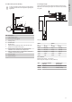

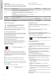
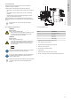
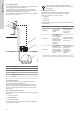
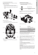


Table Of Contents
- English (GB)
- 1. General information
- 2. Product introduction
- 3. Receiving the product
- 4. Installation requirements
- 5. Mechanical installation
- 6. Electrical connection
- 7. Starting up the product
- 8. Control functions
- 9. Setting the product
- 10. SCALA1 twin booster configuration
- 11. Service
- 12. Starting up after standstill
- 13. Taking the product out of operation
- 14. Storage
- 15. Fault finding
- 15.1 Grundfos Eye SCALA1
- 15.2 The pump does not start
- 15.3 The pump is not running
- 15.4 The pump is running
- 15.5 The pump cuts out during operation
- 15.6 The pump performance is insufficient
- 15.7 The pump starts and stops too frequently
- 15.8 The pump does not stop
- 15.9 The pump gives electric shocks
- 15.10 Twin booster system fault finding
- 15.11 Fault resetting
- 16. Technical data
- 17. Approvals
- 18. Disposing of the product

Duty/Assist
Running in Duty/Assist operation mode brings more flow on the
outlet side, as both pumps can run at the same time. A pump with
an assigned priority will start first and, in case it cannot deliver the
necessary flow, the second pump will start. In case one pump fails
to start, the system will continue running with one pump. The
pumps will switch priority at the start based on the alternation
settings.
Alternation can be set based on runtime or number of starts. This is
done through the Grundfos GO Remote application, either in the
initial setup or through the Settings tab on the Dashboard screen.
"No alternation" is only available for selection when
operating in Duty/Assist.
10.2 Setting SCALA1 twin booster system
WARNING
Electric shock
Death or serious personal injury
‐ Switch off the power supply before you start any work
on the product. Make sure that the power supply
cannot be switched on accidentally.
WARNING
Electric shock
Death or serious personal injury
‐ The protective earth (PE) of the power outlet must be
connected to the protective earth of the pump. The
plug must have the same PE connection system as
the power outlet.
‐
All electrical connections must be carried out by qualified
persons in accordance with local regulations.
If the power cable is damaged, it must be replaced by the
manufacturer, the manufacturer's service partner or a
similarly qualified person.
Make sure that the electrical installation supports the rated
current [A] of the product. See the nameplate of the
product.
Twin base plate, manifolds and communication cable are available
in the SCALA twin accessory set.
To enable the twin operation of two SCALA1 pumps, follow the
steps below.
1. Position both pumps on the twin base plate without fastening
them.
2. Open the cover of both pumps by removing the screws.
3. Punch open the vacant hole/slot on the side of the pump body
and pull one end of the communication cable through the hole.
PUNCH HOLE
TM075385
Punch hole for communication cable
4. Plug in the communication cable in the control board of the
pump.
COMMUNICATION CABLE INPUT
TM075388
Connect communication cable
5. Connect the other end of the communication cable to the
second pump according to the instructions in steps 2 - 4.
6. Fasten both pumps to the base plate.
7. Connect the inlet and outlet manifolds to both pumps.
8. Prime both pumps according to the priming instructions.
TM075386
Fasten pumps to base plate and connect inlet and outlet manifolds
9. Follow the startup instructions.
10. Connect to Grundfos GO Remote and follow the initial setup
screen.
11. Press the connect button on the operating panel of one of the
pumps to establish the connection between the twin pumps
12. Follow the instructions in Grundfos GO Remote for setting up
the twin booster system.
10.2.1
Setting SCALA1 twin booster with Grundfos GO Remote
Setting the twin booster with Grundfos GO Remote can be done in
two ways:
• initial setup: run on first connection, or through the assist tab in
the Dashboard
• settings tab in the Dashboard.
Choose the correct parameters for:
• operation mode
• alternation type
• alteration value.
Examples:
• If the SCALA1 booster system is set up as Duty/Standby with
alternation on the number of starts = 1, this means that every
time the system starts a different pump is running.
• If the SCALA1 booster system is set up as Duty/Standby with
alternation on the number of starts = 5, this means that pump 1
will start first for 5 times before switching the priority to pump 2.
• If the SCALA1 booster system is set up as Duty/Assist with
alternation on runtime = 5h, this means that pump 1 will start
first every time until the system reaches 5 hours of operating
time. Then the priority will be swapped between pumps.
18
English (GB)