
Install Instructions
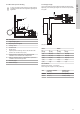

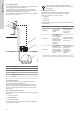


Table Of Contents
- English (GB)
- 1. General information
- 2. Product introduction
- 3. Receiving the product
- 4. Installation requirements
- 5. Mechanical installation
- 6. Electrical connection
- 7. Starting up the product
- 8. Control functions
- 9. Setting the product
- 10. SCALA1 twin booster configuration
- 11. Service
- 12. Starting up after standstill
- 13. Taking the product out of operation
- 14. Storage
- 15. Fault finding
- 15.1 Grundfos Eye SCALA1
- 15.2 The pump does not start
- 15.3 The pump is not running
- 15.4 The pump is running
- 15.5 The pump cuts out during operation
- 15.6 The pump performance is insufficient
- 15.7 The pump starts and stops too frequently
- 15.8 The pump does not stop
- 15.9 The pump gives electric shocks
- 15.10 Twin booster system fault finding
- 15.11 Fault resetting
- 16. Technical data
- 17. Approvals
- 18. Disposing of the product

5.3.3 Mains water pressure boosting
In some countries, boosting from the city water mains is
prohibited. Please follow local regulations regarding this
application.
49
1
37
2
5
10
6
2
3
8
TM075262
Pos. Description
1 Highest tapping point
2 Pipe hangers and supports
3 Isolating valves
4 Flexible hoses
5 Bypass valve
6
Optional pressure-reducing valve on the inlet side if the
pressure can exceed 8 bar (115 psi).
7
Optional pressure relief valve on the outlet side if the
installation cannot withstand the outlet pressure.
8
Drip tray. Install the pump on a small stand to prevent the
ventilation holes from being flooded.
9 Pressure gauge
10 Mains water pipe
5.3.4 Inlet pipe length
The overview below shows the different possible inlet pipe lengths,
depending on the vertical pipe length. The overview is only intended
as a guide.
H
L
Inlet pipe length
DN 32 DN 40
H
[m (ft)]
L
[m (ft)]
H
[m (ft)]
L
[m (ft)]
0 (0) 68 (223) 0 (0) 207 (679)
3 (10) 43 (141) 3 (10) 129 (423)
6 (20) 17 (56) 6 (20) 52 (171)
7 (23) 9 (30) 7 (23) 26 (85)
8 (26) 0 (0) 8 (26) 0 (0)
Pre-conditions:
Maximum flow velocity: 1 l/s (16 gpm).
Inside roughness of pipes: 0.01 mm (0.0004 in).
Size
Inside pipe diameter
[mm (in)]
Pressure loss
[mm (psi/ft)]
DN 32 28 (1.1) 0.117 (5/100)
DN 40 35.2 (1.4) 0.0387 (1.6/100)
11
English (GB)