
Install Instructions

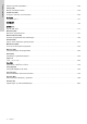
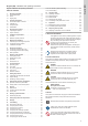
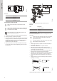
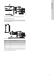
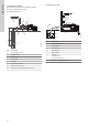
Table Of Contents
- English (GB)
- 1. General information
- 2. Product introduction
- 3. Receiving the product
- 4. Installation requirements
- 5. Mechanical installation
- 6. Electrical connection
- 7. Starting up the product
- 8. Control functions
- 9. Setting the product
- 10. SCALA1 twin booster configuration
- 11. Service
- 12. Starting up after standstill
- 13. Taking the product out of operation
- 14. Storage
- 15. Fault finding
- 15.1 Grundfos Eye SCALA1
- 15.2 The pump does not start
- 15.3 The pump is not running
- 15.4 The pump is running
- 15.5 The pump cuts out during operation
- 15.6 The pump performance is insufficient
- 15.7 The pump starts and stops too frequently
- 15.8 The pump does not stop
- 15.9 The pump gives electric shocks
- 15.10 Twin booster system fault finding
- 15.11 Fault resetting
- 16. Technical data
- 17. Approvals
- 18. Disposing of the product

5.3 Installation examples
We recommend that you follow the installation examples.
Valves are not supplied with the pump.
5.3.1 Suction from a well
6
5
4
2
3
1
H2
H1
TM075006
Pos. Description
1 Highest tapping point
2 Isolating valve
3 Flexible hoses
4 Pipe support
5 Inlet filter
6 Foot valve with strainer
H1 Maximum suction lift: 8 m
H2 Inlet pipe must be submerged at least 0.5 m
5.3.2 Suction from a tank
A
1
2
3
4
6
7
8
5
TM075007
Pos. Description
1 Highest tapping point
2 Pipe hangers
3 Isolating valve
4 Flexible hoses
5 Drain to sewer
6 Inlet filter
7 Freshwater tank
8 Foot valve with strainer
9 Minimum 1-degree inclination
10
English (GB)